Multifunctional signal generator correction method and multifunctional signal generator
A technology for signal generators and calibration methods, applied to instruments, architectures with a single central processing unit, general-purpose stored program computers, etc., to achieve the effects of improving amplitude-frequency characteristics, saving design costs, and reducing logic resources
- Summary
- Abstract
- Description
- Claims
- Application Information
AI Technical Summary
Problems solved by technology
Method used
Image

Examples
Embodiment 1
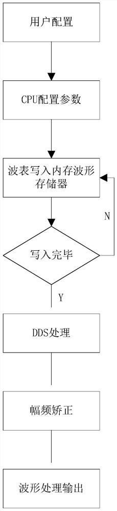
[0042] A multi-function signal generator correction method, including main control unit, FPGA unit, and DAC units;
[0043] The transmission of waveform data, the main control unit transmits wavefront data and configures the frequency of the wavelength data, and transmits the wave form file and frequency to the FPGA unit;
[0044] The correction of the waveform data, the FPGA unit stores and reads the received wavefront data, and calibrates the corrected waveform data to the DAC unit via a web correction algorithm.
[0045] According to the zero-order retention characteristics of the DAC, the amplitude correction is performed before the digital signal input DAC, which is corrected to the amplitude failure, thereby greatly improving the amplitude of the multi-function signal generator system output signal.
[0046]Also included with digital-to-analog conversion, the DAC unit converts the received waveform data into an analog waveform. The waveform data output by the FPGA unit is di...
Embodiment 2
[0051] Based on the first embodiment, the present embodiment also includes a fixed clock source, and a fixed clock source provides a fixed clock to the FPGA unit. By fixing the clock source, a stable clock can be provided so that the entire data is stabilized during transmission.
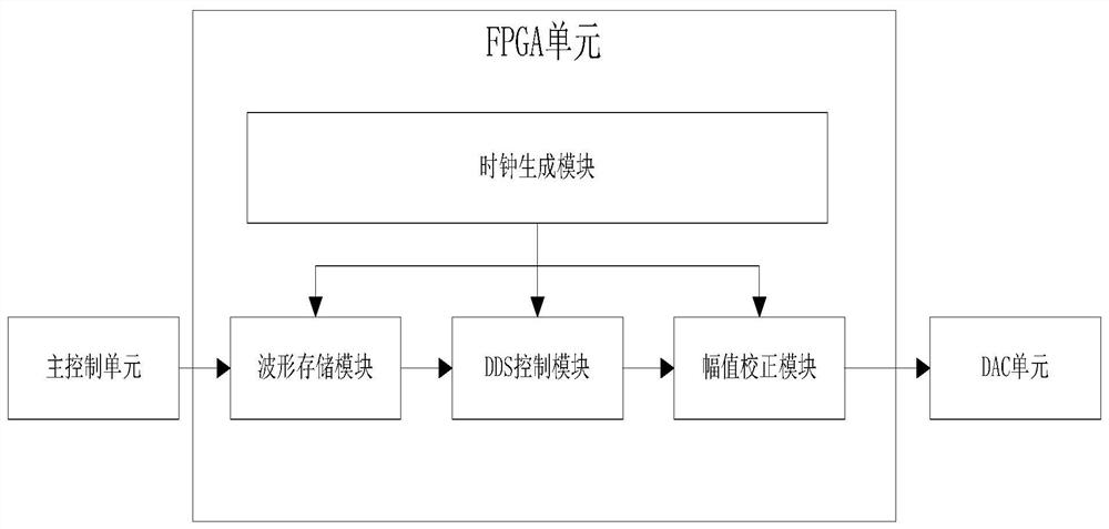
[0052] The FPGA unit includes a clock generation module, a wavelert storage module, a DDS control module, an amplitude correction module; the correction method of waveform data includes,
[0053] The FPGA unit is generated by the clock of the FPGA unit, and the fixed clock source is processed by the clock source to obtain the working clock of the FPGA unit;
[0054] The storage of wavefront data is stored by the wavelert-stored module to store the wavefront data for the wavelength formation of SDPRAM;
[0055] The acquisition of waveform data, the DDS control module obtains the read address of the waveform data according to the frequency configured by the main control unit, and the waveform data corresp...
Embodiment 3
[0059] Multifunctional signal generator, which includes a primary control unit, an FPGA unit, and a DAC unit, the main control unit transmits the waveform data and configures the frequency, and transmits the wavefield file and frequency to the FPGA unit; the FPGA unit performs the received wavefront data Store and read, and calibrate the corrected waveform data to the DAC unit via a magnitude frequency correction algorithm; the DAC unit converts the received waveform data into an analog waveform.
[0060] It also includes a fixed clock source that provides a fixed clock to the FPGA unit.
[0061] The FPGA unit includes clock generation modules, wavelert storage modules, DDS control modules, amplitude correction modules;
[0062] The clock generation module processes the clock provided by the fixed clock source to get the working clock of the FPGA unit;
[0063] The wavelert storage module stores the wavelength data for the wavelength table data;
[0064] The DDS control module per...
PUM
 Abstract
Description
Claims
Application Information
 - R&D
- Intellectual Property
- Life Sciences
- Materials
- Tech Scout
- Unparalleled Data Quality
- Higher Quality Content
- 60% Fewer Hallucinations
Browse by: Latest US Patents, China's latest patents, Technical Efficacy Thesaurus, Application Domain, Technology Topic, Popular Technical Reports.
© 2025 PatSnap. All rights reserved.Legal|Privacy policy|Modern Slavery Act Transparency Statement|Sitemap|About US| Contact US: help@patsnap.com