Molding component and manufacturing method thereof

A manufacturing method and technology of components, applied in inductor/transformer/magnet manufacturing, coil manufacturing, electrical components, etc., can solve the problem of high stress on electrode metallization coating and bare copper, low cost of electronic components, complex inductor manufacturing process, etc. problem, to achieve the effect of improving comprehensive electrical characteristics, simple manufacturing process, improving inductance value and saturation characteristics

Inactive Publication Date: 2021-09-24
SHENZHEN SUNLORD ELECTRONICS
View PDF6 Cites 3 Cited by
  • Summary
  • Abstract
  • Description
  • Claims
  • Application Information

AI Technical Summary

Problems solved by technology

Due to the interaction between different materials, the coating layer of the product is prone to defects such as bubbling and protrusions, and the stress between the electrode metallization coating and the bare copper is large, and the phenomena of floating height and electrode layer peeling are prone to occur during welding, and the welding reliability is poor.
Secondly, the manufacturing process of the inductor is complicated, the production efficiency is low, and the cost is high
[0004] In the prior art, there is a lack of a high-reliability electronic component with simple manufacturing process and low cost and its manufacturing method

Method used


Image

  • Molding component and manufacturing method thereof
  • Molding component and manufacturing method thereof
  • Molding component and manufacturing method thereof

Examples


Embodiment 1

[0063] like Figure 1A-1E As shown, a sheet frame molded component and its manufacturing method, comprising the following steps:

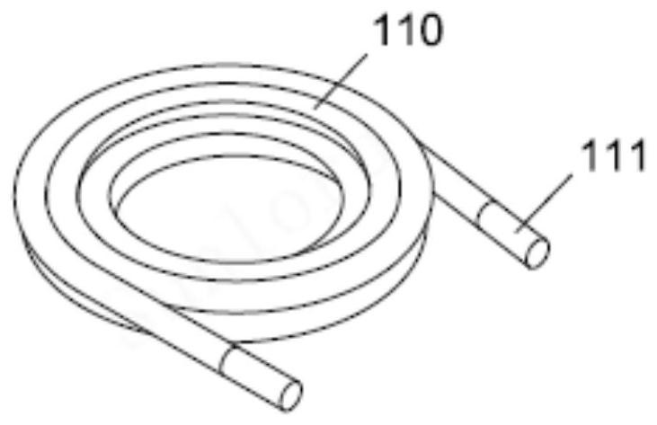
[0064] 1) Making the hollow coil 110

[0065] like Figure 1A , the hollow coil 110 is made of self-adhesive enamelled copper round wire wound in pairs.

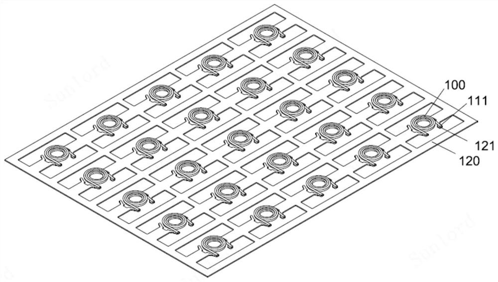
[0066] 2) Spot welding hollow coil and rectangular sheet frame

[0067] Laser spot welding is used to melt the welding corners of the rectangular material frame 120 and the pins 111 of the hollow coil, and the welded assembly after the hollow coil and the material is welded is as follows Figure 1B shown.

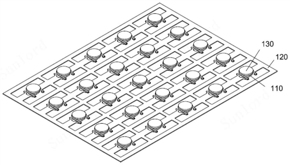
[0068] 3) Implant T-shaped magnetic core

[0069] The T-shaped magnetic core 130 is manufactured by molding and sintering process, and then the central column 131 of the T-shaped magnetic core is implanted into the air-core coil 110. The T-shaped magnetic core is FeSiCr metal soft magnetic powder that has been passivated and insulated. , The magnetic permeability of the magnetic core is p...

Embodiment 2

[0075] like Figure 2A-2E As shown, a material frame type molded inductance bar, its manufacturing method comprises the following steps:

[0076] 1) Make I-shaped magnetic core 210

[0077] like Figure 2A , using molding, cutting and sintering processes to manufacture the I-shaped magnetic core 210, the I-shaped magnetic core is ferrite, the magnetic permeability is preferably 3000-5000, and the saturation magnetic flux is 400-500mT.

[0078] 2) Make air core coil winding

[0079] The flat self-adhesive wires are stacked along the central column of the I-shaped magnetic core 210 to form an air-core coil winding, as shown in 2B, consisting of two parts: the I-shaped magnetic core 210 and the air-core coil 220 .

[0080] 3) The hollow coil winding is welded to the rectangular sheet frame

[0081] Laser spot welding is used to melt the welding corners of the rectangular material frame 230, and cover the pins of the hollow coil 220, and the welded assembly after the hollow co...


PUM


Abstract

The invention relates to a molding component and a manufacturing method thereof, the molding component comprises a hollow coil, a magnetic core, a magnetic plastic package layer and an electrode, the hollow coil is wound on the periphery of the magnetic core, the magnetic core is a pre-sintered magnetic core, and the magnetic plastic package layer is arranged on the periphery of the magnetic core. The magnetic plastic package layer is formed on the hollow coil and the pre-sintered magnetic core in a plastic package mode in a transfer molding or potting mode, and an electrode connected with a lead of the hollow coil is exposed on the outer side of the magnetic plastic package layer. Because the pre-sintered magnetic core is introduced into the molding component, and the magnetic plastic package layer on the coil magnetic core assembly is formed in a transfer molding or potting manner, copper wire damage and deformation and magnetic core fragmentation during a sintering process and cold pressing or hot pressing molding can be effectively avoided; and electrical characteristics such as inductance value and saturation characteristic of a component product can be improved, the product reliability is high, the process is simple, and the cost is low.

Description

technical field [0001] The invention relates to electronic components, in particular to a molded component and a manufacturing method thereof. Background technique [0002] The traditional manufacturing process of blank frame components is generally to wind the coil first, and then perform hot pressing or cold pressing after spot welding. When the hot pressing process is used, the forming temperature is high and the pressure is high. The copper wire is easy to be damaged and desoldered. , the risk of open and short circuits is high, and the yield rate is low; when the cold pressing process is used, the internal density of the product is uneven, cracks are prone to occur, and the product reliability is poor. [0003] The traditional molded inductor process is generally to plastic-enclose a single winding, and it is necessary to insulate the plastic-encapsulated semi-finished product, strip the paint of the coil lead wire, and finally metallize the electrode to form the electr...

Claims


Application Information

Patent Timeline
Patent Type & Authority Applications(China)
IPC IPC(8): H01F17/04H01F27/02H01F27/29H01F41/00H01F41/10
CPCH01F17/04H01F41/005H01F41/00H01F27/022H01F41/10H01F27/29H01F2017/048
Inventor 余鑫树李有云侯勤田姚泽鸿王莹莹夏胜程
Owner SHENZHEN SUNLORD ELECTRONICS
Why Eureka
Try Eureka