Eureka AIR delivers breakthrough ideas for toughest innovation challenges, trusted by R&D personnel around the world.

Multi-layer intelligent drying kiln for ceramic tile production

A drying kiln and intelligent technology, which is applied in the drying of ceramic products, drying solid materials, drying chambers/containers, etc., can solve the problem of uneven heating of bricks, lowering the quality of tile production, and ineffective drying of the contact parts between bricks and installation plates etc. to avoid uneven heating

Active Publication Date: 2021-09-28
佛山市景鑫达陶瓷机械有限公司
View PDF19 Cites 0 Cited by
  • Summary
  • Abstract
  • Description
  • Claims
  • Application Information

AI Technical Summary

Problems solved by technology

[0005] Since the drying of the ceramic body requires a certain drying time, the length of the traditional single-layer or double-layer drying kiln needs to be very long, which in turn requires a certain production plant, resulting in an increase in production costs
[0006] The existing drying kiln is to erect multi-layer bricks in the kiln. By fixing the bricks on the installation board and placing the installation board on the multi-layer shelf in the kiln, the length of the drying kiln can be shortened, but the hot air enters After drying in the kiln, according to the phenomenon that the hot air flow rises and the cold air flow sinks, the dry hot air will accumulate at the top of the drying kiln, and then gradually diffuse to the lower part. Because the bricks on the installation board are stacked in layers, the bricks will be heated in the kiln. Uneven, and the contact part between the brick and the installation plate cannot be effectively dried, thereby reducing the production quality of the tile quality

Method used


Image

  • Multi-layer intelligent drying kiln for ceramic tile production
  • Multi-layer intelligent drying kiln for ceramic tile production
  • Multi-layer intelligent drying kiln for ceramic tile production

Examples


Embodiment

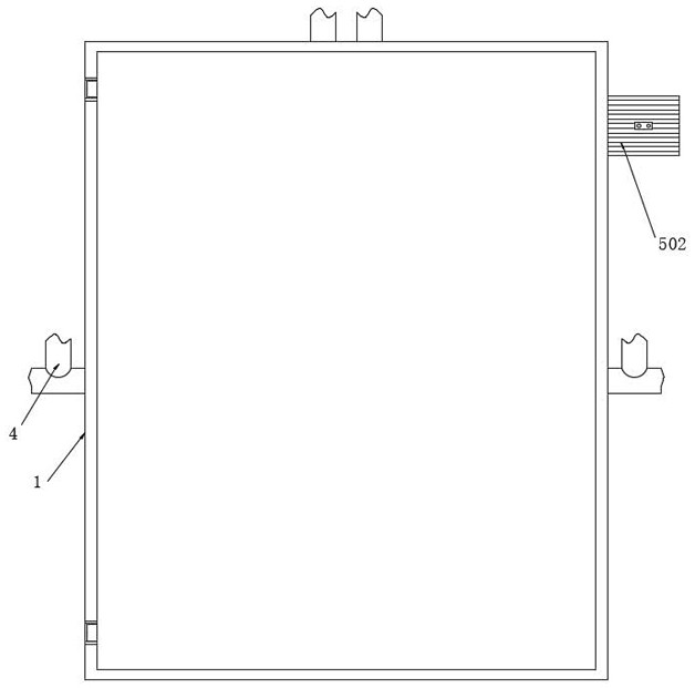
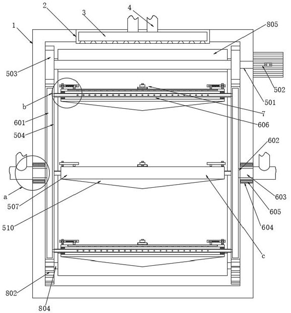
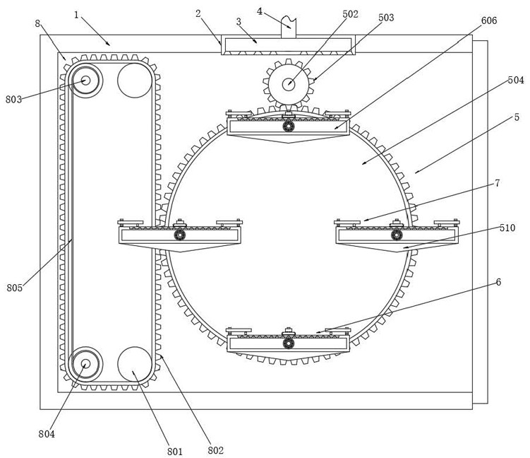
[0039] Example: such as Figure 1-6 As shown, the present invention provides the following technical solutions: a multi-layer intelligent drying kiln for producing ceramic tiles, the multi-layer intelligent drying kiln for producing ceramic tiles includes a kiln 1, an installation hole 2, an exhaust pipe 3, an air intake pipe 4. Uniform drying component 5, drying enhancement component 6;

[0040] The upper end of the kiln 1 is provided with an installation hole 2, and an exhaust pipe 3 is fixedly installed in the installation hole 2, and an inlet pipe 4 is fixedly connected to the input end of the exhaust pipe 3, through which the exhaust pipe 3 can The hot gas conveyed by the air inlet pipe 4 is discharged from the inner upper end of the kiln 1, and the uniform drying assembly 5 is fixedly installed in the kiln 1, and the installation plates 507 of different levels in the kiln 1 can be rotated through the uniform drying assembly 5 , so that the bricks on the mounting plate 5...


PUM


Abstract

The invention relates to the technical field of ceramic drying mechanical equipment for ceramic production, in particular to a multi-layer intelligent drying kiln for ceramic tile production. The multi-layer intelligent drying kiln comprises a kiln body, a uniform drying assembly and drying enhancing assemblies, wherein the uniform drying assembly is fixedly arranged in the kiln body, and the drying enhancing assemblies are arranged on the uniform drying assembly. When tile billets are dried in the kiln body, a driving motor is started, a main gear drives gear discs to synchronously rotate in the kiln body, and fixing pipes are connected between the gear discs, so that mounting plates are driven to rotate through connecting pipes, the tile billets on the mounting plates can be dried by hot air flow jetted by an exhaust pipe, and the overall room temperature favorably rises rapidly; and meanwhile, the hot air flow can enter air cavities I via connecting holes through the connecting pipes, as a large amount of hot air flow flows into the air cavities I, the hot air flow can enter the fixing pipes through communicating holes, then enters air cavities II through air permeation holes and finally flows out through air outlet holes, and the bottoms of the tile billets can be dried.

Description

technical field [0001] The invention relates to the technical field of ceramic drying machinery for producing ceramics, in particular to a multi-layer intelligent drying kiln for producing ceramic tiles. Background technique [0002] The traditional drying kiln adopts a single-layer or double-layer structure. In the field of ceramic production, the daily output of ceramic body drying is directly proportional to the length of the drying kiln: [0003] [0004] (L: drying length, S: drying output, T: drying cycle, W: finished product width) [0005] Since the drying of the ceramic body requires a certain drying time, the length of the traditional single-layer or double-layer drying kiln needs to be very long, which in turn requires a certain production plant, resulting in an increase in production costs. [0006] The existing drying kiln is to erect multi-layer bricks in the kiln. By fixing the bricks on the installation board and placing the installation board on the mult...

Claims


Application Information

Patent Timeline
Patent Type & Authority Applications(China)
IPC IPC(8): F26B11/18F26B21/08F26B25/02F26B25/18
CPCF26B11/181F26B21/001F26B21/004F26B21/083F26B25/02F26B25/18F26B2210/02
Inventor 付志龙
Owner 佛山市景鑫达陶瓷机械有限公司
Why Eureka
Eureka Blog
Learn More