Automatic frying pan

A frying pan, automatic technology, applied in the direction of cooking utensil lids, inserts, cooking utensils, etc., can solve the problems of sticky bottom, flat ingredients sticking to the bottom of the pot, and difficult cleaning of the stir-frying device, so as to reduce production costs , Improve cooking efficiency and reduce heat loss

Pending Publication Date: 2021-10-01
XINXING XIANFENG STAINLESS STEEL PROD MFGR CO LTD
View PDF1 Cites 2 Cited by
  • Summary
  • Abstract
  • Description
  • Claims
  • Application Information

AI Technical Summary

Problems solved by technology

[0003] In the wok of the prior art, the stir-fry device is installed in the pot body to stir-fry the ingredients. The stir-fry device mainly includes a stirring shaft and a stirring paddle. The stirring paddle is fixedly installed at the bottom of the stirring shaft, and the stirring paddle is always kept Place it horizontally. In order to prevent the paddle from rubbing against the bottom of the pot for a long time, the paddle can only be set as close to the bottom of the pot as possible. Therefore, during the stirring process, it is easy to cause a small amount of flat ingredients (such as garlic slices, etc.) to stick to the bottom of the pot. However, the gap between the bottom of the pot and the stirring paddle prevents this part of the ingredients from being stir-fried, and it is prone to sticky bottom problems during long-term heating
[0004] And the stir frying device is installed on the pot cover partly, and the food is stir fried after the pot cover is located on the pot body, but because the stir frying device is fixedly installed on the pot cover, when the user needs to observe the stir frying situation of the food , only the entire pot cover can be opened, the stir-frying device is lifted to stop the stir-frying action, and the action of opening the pot cover will cause a large amount of heat (such as steam) in the pot to be lost, resulting in a decrease in heating efficiency. After combining, it takes a period of heating time to heat up the pot, which will easily lead to unsatisfactory food stir-frying effect, and the stir-frying pot with this structure cannot be disassembled because the stirring device, and even the pot cover is hinged on the pot body, so it is difficult for the stir-frying device. Thorough cleaning, easy to hide dirt
[0005] As shown in the Chinese patent literature, patent No. CN202022163852.6 "a stirring cooking pot with detachable main engine", the main engine and the stirring device are detachably coupled, and the output end of the main engine is arranged on the lid of the pot. The hole on the pot extends into the pot body and connects with the stirring device. This structure can remove the stirring device after use and clean it independently, which can keep the stirring device tidy, but the hole on the pot cover is only suitable for the output end of the main engine to pass through. use, single function
[0006] And the biggest shortcoming of the cooking machines in the above two situations is that in the cooking process, the turning device or the stirring device cannot be disassembled from the pot when the lid is closed. In the pot, it is inconvenient to cook, so it is necessary to further improve the automatic frying pot

Method used


Image

  • Automatic frying pan
  • Automatic frying pan
  • Automatic frying pan

Examples


Embodiment Construction

[0045] The present invention will be further described below in conjunction with the accompanying drawings and embodiments.

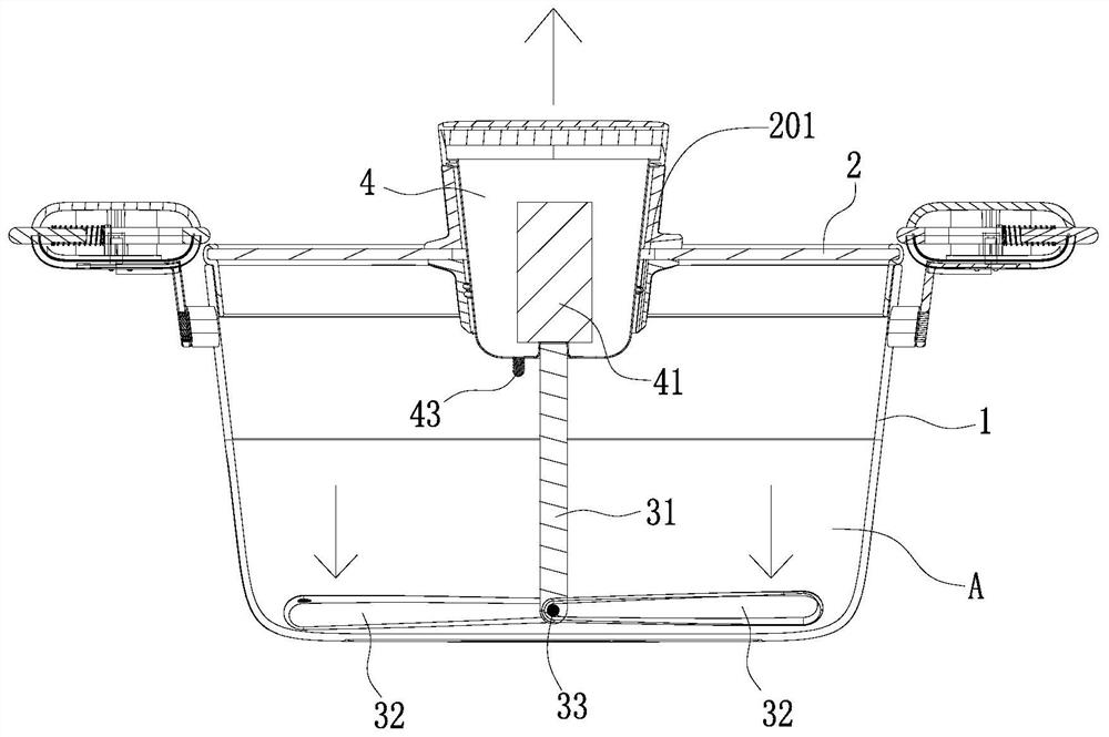
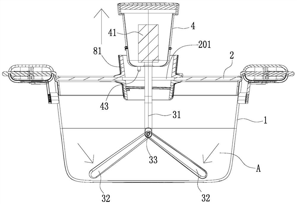
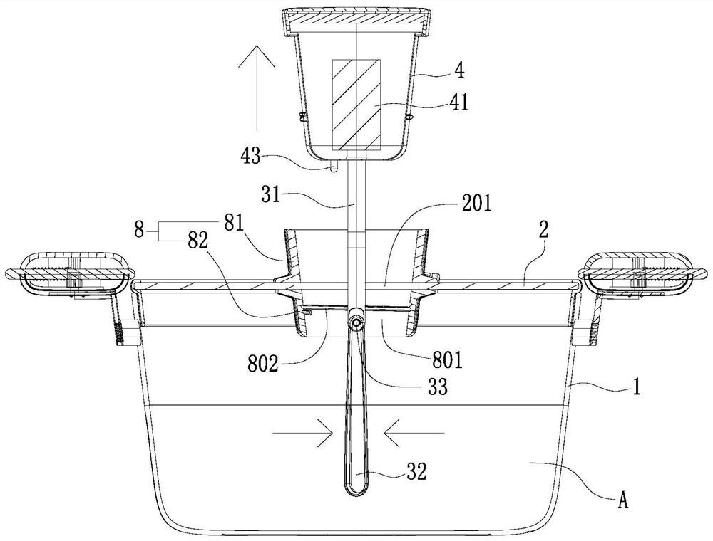
[0046] Such as Figure 1 to Figure 13As shown, an automatic cooking pot includes a pot body 1 and a pot cover 2, the pot cover 2 cooperates with the pot body 1 to form a cooking cavity A, and the stirrer head 4 with a built-in motor 41 is detachably installed on the pot cover 2 , the cooking chamber A is provided with a stirring assembly pivotally connected to the output end of the motor 41, the stirring assembly includes a stirring shaft 31 arranged in the cooking chamber A, the bottom end of the stirring shaft 31 is connected with at least one blade along the vertical direction The stirring paddle 32 that swings freely, the pot cover 2 is provided with an inlet and outlet 201 corresponding to the stirring shaft 31, and the stirring assembly can pass in and out of the cooking chamber A through the inlet and outlet 201, and the stirring blade 32 affecte...


PUM


Abstract

The invention discloses an automatic frying pan. The pan comprises a pan body and a pan cover, the pan cover is matched with the pan body to form a cooking cavity, a stirring machine head with a built-in motor is detachably installed on the pan cover, and a stirring assembly pivoted with the output end of the motor is arranged in the cooking cavity. The pan is characterized in that: the stirring assembly comprises a stirring shaft arranged in the cooking cavity, the bottom end of the stirring shaft is connected with at least one stirring paddle freely swinging in the vertical plane direction, the pan cover is provided with an access corresponding to the stirring shaft, and the stirring assembly can enter and exit the cooking cavity through the access. According to the frying pan of the structure, in the cooking process, under the condition that the pan cover is not opened, a user can put the stirring assembly into the cooking cavity or draw the stirring assembly out of the cooking cavity according to needs, so that the temperature of the cooking cavity can be kept, heat loss is reduced, the cooking efficiency is improved, and after the stirring assembly is detached, the access can be used as a food feeding opening to put food materials into the cooking cavity.

Description

technical field [0001] The invention relates to the field of cooking utensils, in particular to an automatic cooking pot. Background technique [0002] As the pace of people's life is getting faster and faster, work, leisure and entertainment, and family life are becoming more and more confused. In order to solve the problem of cooking and cooking, an automatic cooking pot appears on the market. Just put a certain amount of ingredients into the automatic cooking In the pot, the ingredients are automatically stir-fried through the built-in stirring device in the pot, and the next thing for the user is to wait for the delicious meals to be served. [0003] In the wok of the prior art, the stir-fry device is installed in the pot body to stir-fry the ingredients. The stir-fry device mainly includes a stirring shaft and a stirring paddle. The stirring paddle is fixedly installed at the bottom of the stirring shaft, and the stirring paddle is always kept Place it horizontally. In...

Claims


Application Information

Patent Timeline
Patent Type & Authority Applications(China)
IPC IPC(8): A47J36/08A47J36/16A47J27/00
CPCA47J36/165A47J27/002A47J36/08
Inventor 叶灿雄叶逾梁建秀梅贵涛
Owner XINXING XIANFENG STAINLESS STEEL PROD MFGR CO LTD
Why Eureka
Try Eureka