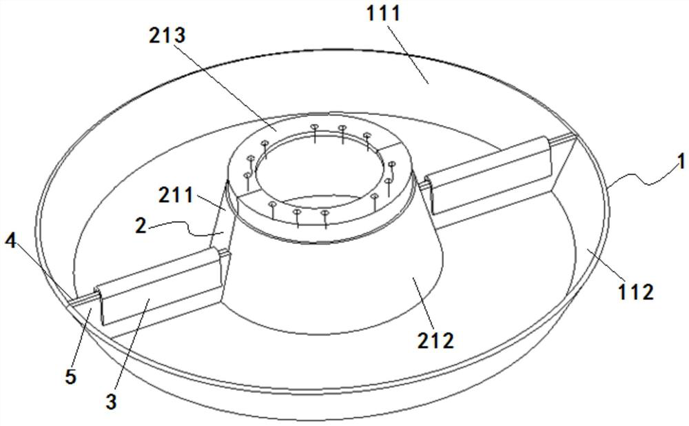
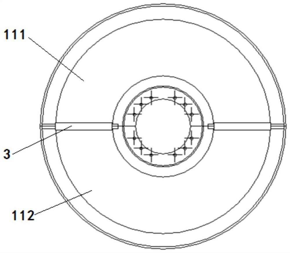
Material receiving disc for directional solidification crystallization furnace and manufacturing method of material receiving disc
A technology of directional solidification and receiving trays, which is applied in the direction of manufacturing tools, casting equipment, casting molding equipment, etc., can solve the problems of burns on furnace walls and other parts of equipment, reduced vacuuming capacity of directional furnaces, and easy generation of splashes, etc., to achieve improved The effect of service life and equipment utilization, easy cleaning, and low cost
- Summary
- Abstract
- Description
- Claims
- Application Information
AI Technical Summary
Problems solved by technology
Method used
Image
Examples
Embodiment 1
[0059] The chemical composition of the alloy material used for pouring the working blades of a high-pressure turbine is 60% Ni, 10.5% Co, 9.3% Cr, and 20.2% other elements. In the actual pouring process, splashing is very easy to occur. Taking pouring of 100 sets of mold shells as an example, the failure rate of pouring equipment is 1%, and the rate of slag inclusion is 15%.
[0060] By adopting the material receiving tray design method described in the invention, the corresponding material receiving tray is prepared. The material receiving tray adopts the angle σ1 between the side inner wall of the material receiving tray main body and the bottom inner wall of the material receiving tray main body as 120°, the maximum outer diameter D1 of the top end surface of the material receiving tray main body is 547mm, and the bottom of the material receiving tray main body The outer diameter D3 of the outer wall plane is 470 mm, and the height H1 from the top end surface of the receivi...
Embodiment 2
[0062] The chemical composition of the alloy material used for pouring the guide vane of a high-pressure turbine is 52.1% Co, 11.5% Ni, 26.5% Cr, and 9.9% other elements. In the actual pouring process, splashing is very easy to occur. Taking pouring of 50 sets of mold shells as an example, the failure rate of pouring equipment is 1%, and the slag inclusion rate is 24.5%.
[0063] By adopting the material receiving tray design method described in the invention, the corresponding material receiving tray is prepared. The material receiving tray adopts the angle σ1 between the side inner wall of the material receiving tray main body and the bottom inner wall of the material receiving tray main body as 110°, the maximum outer diameter D1 of the top end surface of the material receiving tray main body is 500mm, and the bottom of the material receiving tray main body The outer diameter D3 of the outer wall plane is 450 mm, and the height H1 from the top end surface of the receiving t...
Embodiment 3
[0065] The chemical composition of the alloy material used for pouring the working blade of the first-stage turbine of a machine is 63.5% Ni, 8.0% Co, 7.1% Cr, and 21.4% other elements. In the actual pouring process, splashing is very easy to occur. Taking pouring of 100 sets of mold shells as an example, the failure rate of pouring equipment is 1%, and the rate of slag inclusion is 15%.
[0066] By adopting the material receiving tray design method described in the invention, the corresponding material receiving tray is prepared. The material receiving tray adopts the angle σ1 between the side inner wall of the material receiving tray main body and the bottom inner wall of the material receiving tray main body as 115°, the maximum outer diameter D1 of the top end surface of the material receiving tray main body is 525mm, and the bottom of the material receiving tray main body The outer diameter D3 of the outer wall plane is 460 mm, and the height H1 from the top end surface o...
PUM
| Property | Measurement | Unit |
|---|---|---|
| Maximum outer diameter | aaaaa | aaaaa |
| Height | aaaaa | aaaaa |
| Thickness | aaaaa | aaaaa |
Abstract
Description
Claims
Application Information
 - R&D
- Intellectual Property
- Life Sciences
- Materials
- Tech Scout
- Unparalleled Data Quality
- Higher Quality Content
- 60% Fewer Hallucinations
Browse by: Latest US Patents, China's latest patents, Technical Efficacy Thesaurus, Application Domain, Technology Topic, Popular Technical Reports.
© 2025 PatSnap. All rights reserved.Legal|Privacy policy|Modern Slavery Act Transparency Statement|Sitemap|About US| Contact US: help@patsnap.com


