A method for predicting tool wear and remaining life

A technology for tool wear and life prediction, applied in neural learning methods, genetic laws, manufacturing tools, etc., can solve the problem that it is difficult to guarantee the prediction accuracy with a single information

Active Publication Date: 2022-03-11
TAIYUAN UNIVERSITY OF SCIENCE AND TECHNOLOGY
View PDF11 Cites 0 Cited by
  • Summary
  • Abstract
  • Description
  • Claims
  • Application Information

AI Technical Summary

Problems solved by technology

Most of the existing tool indirect monitoring methods are based on a certain parameter signal to establish a mapping relationship, and it is difficult to guarantee the prediction accuracy with a single information

Method used


Image

  • A method for predicting tool wear and remaining life
  • A method for predicting tool wear and remaining life
  • A method for predicting tool wear and remaining life

Examples


Embodiment Construction

[0081] Embodiment of the present invention will be further described below in conjunction with accompanying drawing:

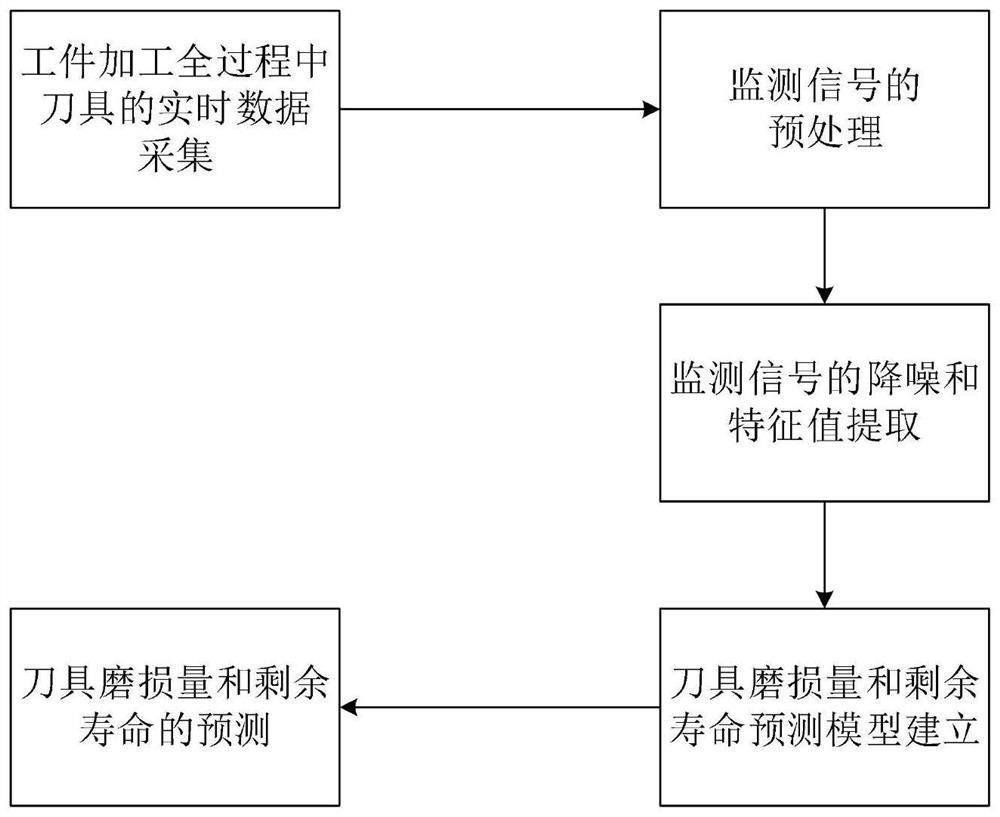
[0082] In the embodiment of the present invention, the improved Elman neural network tool wear amount and remaining life prediction method based on multi-sensor information fusion, the method flow chart is as follows figure 1 shown, including the following steps:

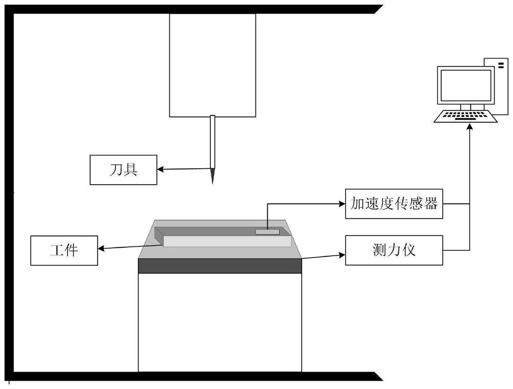
[0083] Step 1), build an experimental platform, and obtain real-time monitoring data reflecting the state of the tool;

[0084] The workbench is built as figure 2 shown. The vibration signal of this experiment is collected by IEPE piezoelectric acceleration sensor; the cutting force signal is collected by Kistler9225B three-way dynamometer. The vibration signal is generated because the tool is in contact with the workpiece during processing, so the acceleration sensor is installed on the workpiece; the cutting force signal is the force applied by the tool to the workpiece for cutting, so the dyn...


PUM


Abstract

A method for predicting tool wear and remaining life, which belongs to the technical field of mechanical reliability, and its implementation steps are as follows: 1. Install a dynamometer and an acceleration sensor on a cutting experiment platform to obtain real-time monitoring data reflecting the state of the tool; 2. The collected cutting force signal and vibration signal are preprocessed; 3. Noise reduction and feature extraction are performed on the preprocessed signal; 4. The genetic algorithm is combined with the double hidden layer Elman neural network to establish a fast convergence and prediction accuracy Highly improved Elman neural network prediction model; 5, train the prediction model, and use the prediction model to predict tool wear and remaining life at the same time, the advantage of the present invention is to obtain tool status information in real time during tool processing, to ensure reliable and effective operation of the process .

Description

technical field [0001] The invention belongs to the technical field of mechanical reliability, and in particular relates to a method for predicting tool wear and remaining life. Background technique [0002] The tool is the executor of the cutting process. The real-time status of the tool during the cutting process directly affects the machining quality, machining accuracy and machining efficiency of the part, and even causes serious obstacles to the entire machining system, resulting in huge economic losses. Due to the lack of real-time perception of the tool state, the conventional NC machining technology only processes according to the given workpiece geometric contour, processing parameters, and tool path, and does not take the tool state change into consideration, so it cannot be based on the machining process. The change of the tool state can give early warning in time, which cannot guide the adjustment of process parameters in the process of processing, which directly...

Claims


Application Information

Patent Timeline
Patent Type & Authority Patents(China)
IPC IPC(8): B23Q17/09G06F30/17G06F30/27G06N3/04G06N3/08G06N3/12G06F119/02G06F119/14
CPCB23Q17/0957B23Q17/0995B23Q17/0966B23Q17/0971G06F30/17G06F30/27G06N3/04G06N3/08G06N3/126G06F2119/02G06F2119/14
Inventor 陈高华周子涵丁庆伟
Owner TAIYUAN UNIVERSITY OF SCIENCE AND TECHNOLOGY
Why Eureka
Try Eureka