Wavelength selection filter, method of manufacturing wavelength selection filter, and display device
A wavelength selection and optical filter technology, which is applied in the manufacture of semiconductor/solid-state devices, optical components used to change the spectral characteristics of emitted light, filters, etc. The effect of suppressing color mixing
- Summary
- Abstract
- Description
- Claims
- Application Information
AI Technical Summary
Problems solved by technology
Method used
Image

Examples
no. 1 Embodiment approach
[0044] refer to Figure 1 to Figure 12 The first embodiment will be described. The first embodiment is an embodiment of a wavelength selective filter and a method of manufacturing the wavelength selective filter. The wavelength selective filter has a function of extracting light in a specific wavelength range from light incident on the wavelength selective filter by reflection or transmission. The wavelength range to be selected by the wavelength selection filter is not particularly limited. For example, the wavelength selection filter extracts light in a specific wavelength range from light that can be visually recognized by human eyes, that is, light in the visible range. Below, the wavelength of light in the visible region is greater than or equal to 400 nm and less than or equal to 800 nm.
[0045] [Overall structure of wavelength selective filter]
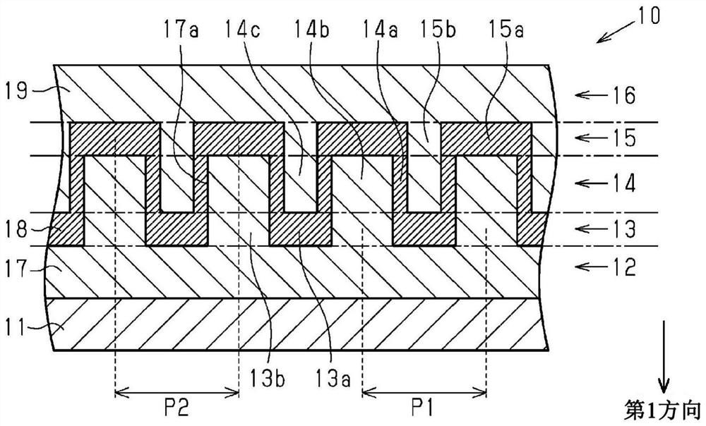
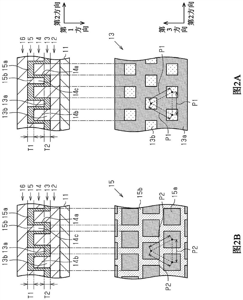
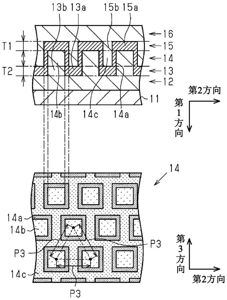
[0046] Such as figure 1 As shown, the wavelength selection filter 10 has a substrate 11 , a first low-refractive index r...
no. 2 Embodiment approach
[0161] refer to Figure 13 to Figure 16 A second embodiment will be described. The second embodiment is an embodiment of a wavelength selective filter and a method of manufacturing the wavelength selective filter. Hereinafter, the difference between the second embodiment and the first embodiment will be mainly described, and the same components as those in the first embodiment will be given the same reference numerals and their descriptions will be omitted.
[0162] [Structure of wavelength selective filter]
[0163] refer to Figure 13 and Figure 14 The structure of the wavelength selection filter of the second embodiment will be described. Such as Figure 13 As shown, the wavelength selection filter 20 of the second embodiment has two resonant structure parts 21, that is, the resonant structure part 21 is composed of the first low-refractive index region 12 and the first lattice described in the first embodiment. A structure composed of the grating region 13 , the int...
no. 3 Embodiment approach
[0197] refer to Figure 17 and Figure 18 A third embodiment will be described. The third embodiment is an embodiment of a display device.
[0198] [Structure of Display Device]
[0199] Such as Figure 17 As shown, the display device 100 has a reflection layer 1 , a light source layer 2 , a wavelength conversion layer 3 , a wavelength selection layer 4 , and a drive unit 5 . The wavelength conversion layer 3 is located on the light source layer 2 , and the wavelength selection layer 4 is located on the wavelength conversion layer 3 . The reflective layer 1 is located under the light source layer 2 , that is, on the opposite side of the wavelength conversion layer 3 with respect to the light source layer 2 . The drive unit 5 is connected to the light source layer 2 . The side where the wavelength selective layer 4 is located relative to the light source layer 2 is the front side of the display device 100 , and the side where the reflective layer 1 is located relative to ...
PUM
| Property | Measurement | Unit |
|---|---|---|
| depth | aaaaa | aaaaa |
| thickness | aaaaa | aaaaa |
| reflectance | aaaaa | aaaaa |
Abstract
Description
Claims
Application Information
 - R&D
- Intellectual Property
- Life Sciences
- Materials
- Tech Scout
- Unparalleled Data Quality
- Higher Quality Content
- 60% Fewer Hallucinations
Browse by: Latest US Patents, China's latest patents, Technical Efficacy Thesaurus, Application Domain, Technology Topic, Popular Technical Reports.
© 2025 PatSnap. All rights reserved.Legal|Privacy policy|Modern Slavery Act Transparency Statement|Sitemap|About US| Contact US: help@patsnap.com