
Supercritical carbon dioxide injection device

A carbon dioxide and injection device technology, applied in the direction of explosion generation device, used abrasive processing device, spray gun, etc., can solve the problems of labor, operator accidental injury, difficult adjustment, etc., to achieve convenient oiling and maintenance, prolong service life, The effect of high flexibility

Inactive Publication Date: 2021-10-15
陕西工业职业技术学院
View PDF0 Cites 0 Cited by
  • Summary
  • Abstract
  • Description
  • Claims
  • Application Information

AI Technical Summary

Problems solved by technology

[0002] Supercritical carbon dioxide is a carbon dioxide fluid maintained above the critical temperature and critical pressure. Supercritical carbon dioxide has the advantages of non-toxicity, low price, wide range of sources, low critical temperature, and chemical inertness. It is one of the commonly used supercritical fluids in industry. It is widely used as a solvent for synthetic reactions and as an extractant for extracting natural products. In industry, the efficiency of supercritical carbon dioxide for high-pressure impact to break rocks is higher than that of water for high-pressure impact to achieve rock breakage, but the existing injection devices can only For straight jet impact, it is necessary to adjust the impact direction of the fluid in order to improve the crushing efficiency. It is difficult to adjust and it is extremely laborious. In addition, during the impact crushing operation, the splashing of the broken rock and fluid will cause accidental injury to the operators on the crushing site. So people need a supercritical carbon dioxide injection device to solve the problems in the prior art

Method used


Image

  • Supercritical carbon dioxide injection device
  • Supercritical carbon dioxide injection device
  • Supercritical carbon dioxide injection device

Examples


Embodiment Construction

[0029] The following will clearly and completely describe the technical solutions in the embodiments of the present invention with reference to the accompanying drawings in the embodiments of the present invention. Obviously, the described embodiments are only some, not all, embodiments of the present invention. Based on the embodiments of the present invention, all other embodiments obtained by persons of ordinary skill in the art without making creative efforts belong to the protection scope of the present invention.

[0030] see Figure 1-7 , the present invention provides technical solutions:

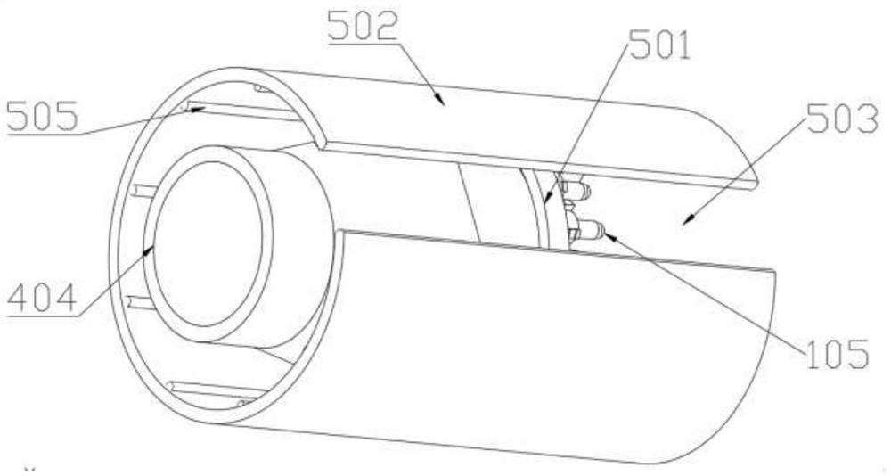
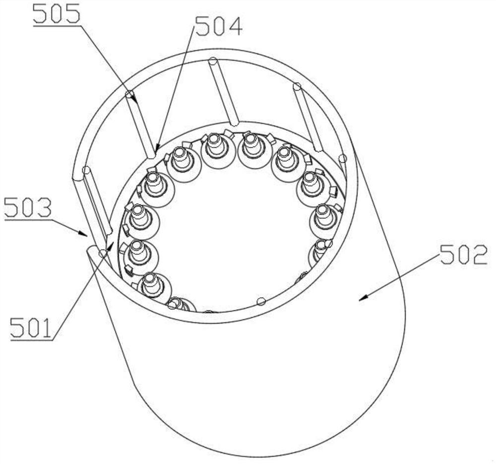
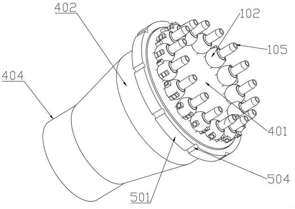
[0031] A supercritical carbon dioxide injection device, including a variable flow guide assembly, a first orientation assembly, a second orientation assembly, a pressurized drainage assembly, and a splash protection assembly. The variable flow guide assembly includes a sub-inlet pipe 101 and a spherical groove support body 102 , spherical pipe 103, injection outlet pipe 104, spray ...


PUM


Abstract

The invention discloses a supercritical carbon dioxide injection device. The device comprises a direction-changing flow guide component, a first orientation component and a second orientation component, wherein the first orientation component is arranged in the direction-changing flow guide component, and the second orientation component is arranged in the direction-changing flow guide component. According to the device, wall breaking and rock crushing operation is conducted by utilizing the impact force of high-pressure fluid, the rock strength can be reduced through supercritical carbon dioxide jet injection, the rock crushing efficiency is far higher than that of water jet rock crushing efficiency, and in the supercritical carbon dioxide jet rock crushing process, an operator can control a first electromagnet, a second electromagnet, a third electromagnet and a fourth electromagnet through a PLC, s so that an injector head conducts jet rock crushing in different directions, and the crushing efficiency is greatly improved; and a sliding shielding shell is designed, jet supercritical carbon dioxide and rock particles subjected to impact crushing can be isolated and shielded in multiple directions, and the situation that nearby workers are accidentally injured by sputtering can be avoided.

Description

technical field [0001] The invention relates to the field of mechanical technology, in particular to a supercritical carbon dioxide injection device. Background technique [0002] Supercritical carbon dioxide is a carbon dioxide fluid maintained above the critical temperature and critical pressure. Supercritical carbon dioxide has the advantages of non-toxicity, low price, wide range of sources, low critical temperature, and chemical inertness. It is one of the commonly used supercritical fluids in industry. It is widely used as a solvent for synthetic reactions and as an extractant for extracting natural products. In industry, the efficiency of supercritical carbon dioxide for high-pressure impact to break rocks is higher than that of water for high-pressure impact to achieve rock breakage, but the existing injection devices can only For straight jet impact, it is necessary to adjust the impact direction of the fluid in order to improve the crushing efficiency. It is diffic...

Claims


Application Information

Patent Timeline
Patent Type & Authority Applications(China)
IPC IPC(8): B24C1/00B24C5/04B24C9/00
CPCB24C1/003B24C9/00B24C5/04
Inventor 李文军强华王锟张琳胡平
Owner 陕西工业职业技术学院
Learn More