
Device facilitating mold stripping for fabricated building

A construction and assembly technology, applied in the direction of unloading devices, manufacturing tools, etc., can solve the problems of scrapped prefabricated parts, the overall appearance of prefabricated parts is not on the same level, bending and deformation of prefabricated parts mold, etc., to improve the efficiency of mold release and speed effect

Inactive Publication Date: 2021-10-19
徐州中煤汉泰建筑工业化有限公司
View PDF11 Cites 1 Cited by
  • Summary
  • Abstract
  • Description
  • Claims
  • Application Information

AI Technical Summary

Problems solved by technology

[0003] The object of the present invention is to address the deficiencies of the prior art, and provide a mold ejection device for prefabricated buildings, so as to solve the problem of separating the prefabricated parts from the mold by knocking the employees proposed in the background technology. During the knocking process, it is easy to cause the prefabricated part mold to bend and deform, so that the overall appearance of the prefabricated part is not at the same level, which in turn causes the prefabricated part to be scrapped and unusable, and the existing prefabricated part molds are placed on the ground. Bend on the ground to place steel bars inside the prefabricated part molds, resulting in employees bending over for a long time, which not only reduces the overall work efficiency, but also easily causes lumbar muscle strain and intervertebral disc herniation, which affects the normal physical and mental health of employees, and the overall The prefabricated part mold is installed indoors, which causes the problem of long drying time and low drying efficiency of prefabricated parts

Method used


Image

  • Device facilitating mold stripping for fabricated building
  • Device facilitating mold stripping for fabricated building
  • Device facilitating mold stripping for fabricated building

Examples


Embodiment Construction

[0030]The following will clearly and completely describe the technical solutions in the embodiments of the present invention with reference to the accompanying drawings in the embodiments of the present invention. Obviously, the described embodiments are only some, not all, embodiments of the present invention. Based on the embodiments of the present invention, all other embodiments obtained by persons of ordinary skill in the art without making creative efforts belong to the protection scope of the present invention.

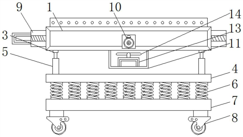
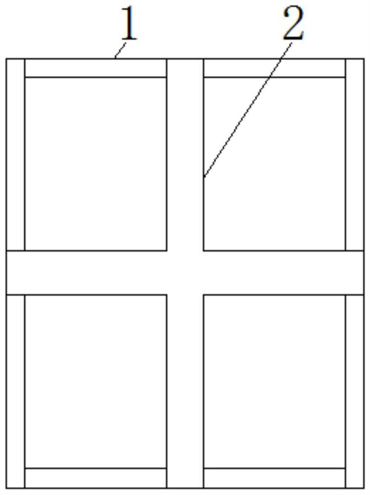
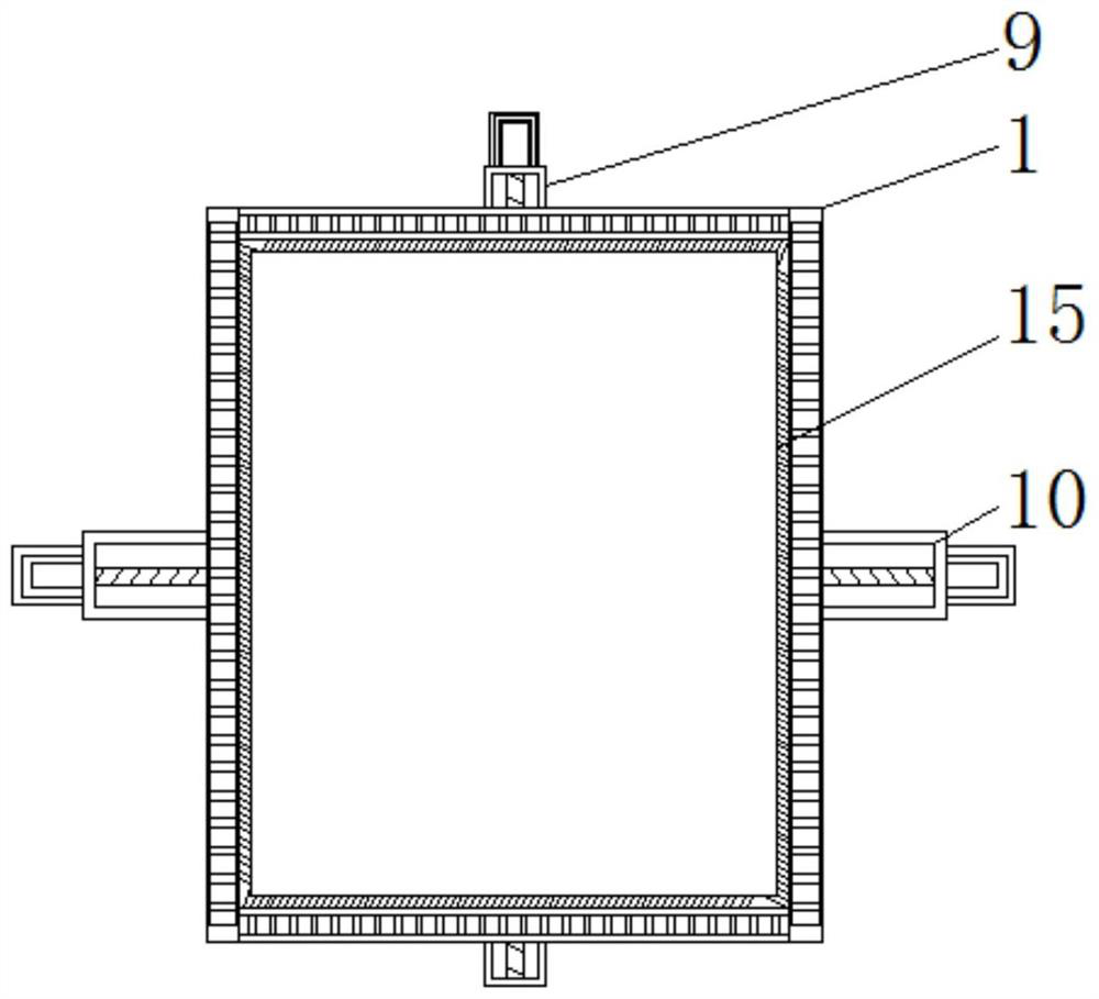
[0031] see Figure 1-7 , the present invention provides a technical solution: a device for easy mold ejection for prefabricated buildings, such as figure 1 , figure 2 , image 3 , Figure 4 with Figure 7 As shown, the installation groove 2 is opened through the bottom of the installation platform 1, and the connection block 3 is welded and fixed on the bottom of the installation platform 1, the top of the load bearing plate 4 is fixedly connected with the...


PUM


Abstract

The invention discloses a device facilitating mold stripping for a fabricated building. The device comprises a mounting table, a bearing plate, a vertical mold stripping device, a transverse mold stripping device, a through frame, a rotating motor and an anti-sticking plate, wherein a mounting groove is formed in the bottom of the mounting table in a penetrating mode, and the top end of the bearing plate is fixedly connected with the bottom of a hydraulic cylinder. The device facilitating mold stripping for the fabricated building is provided with movable wheels, the mounting table is pushed to drive the movable wheels to move so as to move an overall prefabricated part mold outdoors for prefabricated part pouring treatment, thus, the circumstance that the overall prefabricated part mold is fixed at the same position for a long time, so that the overall drying period is long and the drying efficiency is low after the prefabricated part is poured is avoided, meanwhile, through external air drying and sunlight irradiation, the drying period of the prefabricated part is shortened, the drying efficiency of the prefabricated part mold is improved, and the production efficiency of the prefabricated part is sequentially improved.

Description

technical field [0001] The invention relates to the technical field of prefabricated buildings, in particular to a mold ejection device for prefabricated buildings. Background technique [0002] Prefabricated buildings are buildings assembled from prefabricated parts and components on site. They are called prefabricated buildings. According to the form and construction method of prefabricated components, they are divided into block buildings, plate buildings, box buildings, skeleton plate buildings and rising boards. Buildings and other five types, with the development of modern industrial technology, building houses can be manufactured in batches like machine production, as long as the prefabricated house components are transported to the construction site and assembled. A large number of assembly operations are greatly reduced compared with the original cast-in-place operation, but the existing prefabricated buildings need to prefabricate the prefabricated parts through th...

Claims


Application Information

Patent Timeline
Patent Type & Authority Applications(China)
IPC IPC(8): B28B13/06
CPCB28B13/06
Inventor 吴锋董晨徐臣侯先举
Owner 徐州中煤汉泰建筑工业化有限公司
Learn More