Hydraulic control system of tractor suspension mechanism

A technology of hydraulic control system and suspension mechanism, which is applied to agricultural machinery and tools, agricultural machinery, mechanical equipment, etc. It can solve the problems of affecting work efficiency, affecting the work efficiency of plow tools and other agricultural tools on arable land, and poor connection stability of agricultural tools. The effect of improving stability

Active Publication Date: 2021-10-22
山东悍沃农业装备有限公司
View PDF9 Cites 2 Cited by
  • Summary
  • Abstract
  • Description
  • Claims
  • Application Information

AI Technical Summary

Problems solved by technology

[0003] However, due to the non-uniform size of the connecting parts of farm tools such as plow tools, the existing hydraulically controlled suspension mechanism cannot be reasonably adjusted according to the size of the farm tool to meet the connection requirements of different farm tools, and the traditional suspension mechanism has poor connection stability for farm tools. This further affects the working efficiency of farm tools such as plows on cultivated land. Therefore, the purpose of the present invention is a hydraulic control system for a tractor suspension mechanism to solve the problem that the existing suspension mechanism cannot be reasonably adjusted according to the size of the farm tool to meet the connection requirements of different farm tools. Moreover, the connection stability of traditional suspension mechanisms to farm tools is poor, which in turn affects the work efficiency of farm tools such as plows on cultivated land.

Method used


Image

  • Hydraulic control system of tractor suspension mechanism
  • Hydraulic control system of tractor suspension mechanism
  • Hydraulic control system of tractor suspension mechanism

Examples


Embodiment 1

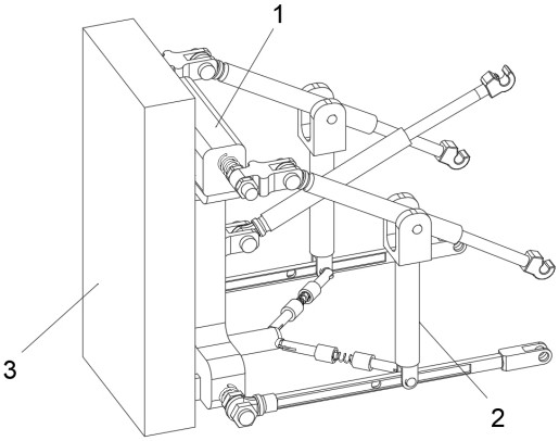
[0059] see Figure 1-Figure 16 As shown, the purpose of this embodiment is to provide a tractor suspension mechanism hydraulic control system, including a support 1 and a suspension mechanism 2 installed on the support 1, and the suspension mechanism 2 at least includes:

[0060] Limiting rod 202, limit chute 2021 is provided at the center of the side wall surface at both ends of the limiting rod 202, and one end of the limiting rod 202 is fixedly connected with the first limiting rod connecting ear 2022, the first limiting rod connecting ear 2022 A limit rod hinge hole 2023 is opened on the top, and the other end of the limit rod 202 is fixedly connected with a second limit rod connecting ear 2024;

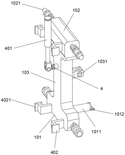
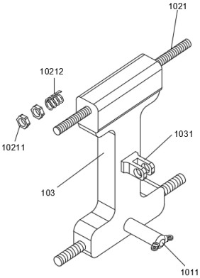
[0061] When the limit rod 202 of this embodiment is actually used, according to the size of the plow, the two second limit rod connecting ears 2024 are respectively nested on the screw rods 1021 on both sides of the lower fixed arm 101, and the two are adjusted according to the s...

Embodiment 2

[0079] In the actual operation process, the hydraulic load-bearing rod 201 is connected to the plow through the load-bearing rod connecting part 2011, but during the connection process, the load-bearing rod connecting part 2011 may be deformed due to the load force, making it unable to fully fit the plow tool. In order to further ensure the safe distance between the load-bearing rod connector 2011 and the gap between the plow, the load-bearing rod connector 2011 is provided with a connecting ring 20111, the connecting ring 20111 is a ring structure with an open top, and the upper half ring of the connecting ring 20111 is fixedly installed There is a laser emitting element 20112, one side of the laser emitting element 20112 is connected with a photoelectric element, the photoelectric element is used to collect the laser light after turning back, and the laser emitting element 20112 is set to emit the laser light to the lower semicircle on the other side of the load-bearing rod co...


PUM


Abstract

The invention relates to the technical field of tractor suspension, in particular to a hydraulic control system of a tractor suspension mechanism. The system comprises limiting rods, limiting sliding grooves are formed in the centers of the surfaces of the side walls of the two ends of the limiting rods, one end of the limiting rods is fixedly connected with a first limiting rod connecting lug, a limiting rod hinge hole is formed in the first limiting rod connecting lug, the other end of the limiting rods is fixedly connected with a second limiting rod connecting lug, and the top end of a buffer rod is fixedly connected with a second hinge seat. By arranging a screw rod, the limiting rods and a hydraulic lifting rod are arranged on the screw rod, and the positions of the limiting rods and the hydraulic lifting rod are adjusted through locking nuts, so that the distance between suspension mechanisms is adjusted, and the connection requirement for connection of agricultural tools such as ploughs of different sizes can be met. A stretching rod is arranged, the limiting rods are stabilized and damped through a third spring, and the two limiting rods draw close to each other, so that the plough is clamped and fixed, and the stability of fixing the plough is improved.

Description

technical field [0001] The invention relates to the technical field of tractor suspension, in particular to a hydraulic control system of a tractor suspension mechanism. Background technique [0002] The tractor suspension mechanism is the main device for the tractor to pull farm tools for agricultural operations. The suspension mechanism is the connecting rod between the farm tool and the tractor. Through the hydraulic connection rod, the lifting, lowering and working position adjustment of the farm tool can be realized. It is an essential part of the tractor. important components. [0003] However, due to the non-uniform size of the connecting parts of farm tools such as plow tools, the existing hydraulically controlled suspension mechanism cannot be reasonably adjusted according to the size of the farm tool to meet the connection requirements of different farm tools, and the traditional suspension mechanism has poor connection stability for farm tools. This further affec...

Claims


Application Information

Patent Timeline
Patent Type & Authority Applications(China)
IPC IPC(8): A01B59/06A01B63/102F16F15/02F16F15/023F16F15/067
CPCA01B59/06A01B63/102F16F15/067F16F15/023F16F15/022
Inventor 毛小亮孙士元王翠平邓琪
Owner 山东悍沃农业装备有限公司
Why Eureka
Try Eureka