Retina operation auxiliary device based on optical coherence elastic imaging system

An elastography and optical coherence technology, used in surgery, ophthalmic surgery, stereotaxic surgical instruments, etc., can solve the problems of body shaking, low safety, affecting the operation of the operation, etc., to achieve the effect of high safety and reduced wear and tear

Inactive Publication Date: 2021-10-22
黄国富
View PDF0 Cites 1 Cited by
  • Summary
  • Abstract
  • Description
  • Claims
  • Application Information

AI Technical Summary

Problems solved by technology

[0004] In order to overcome the shortcomings that the doctor will use tweezers to lift the patient's eyelids when the patient is undergoing retinal surgery, which is not safe, and the patient's body may shake when the anesthesia effect is about to end, which will affect the operation. The technology to be solved Problem: Provide a retinal surgery assisting device based on an optical coherent elastography system that can automatically lift the patient's eyelids and fix the patient's body

Method used


Image

  • Retina operation auxiliary device based on optical coherence elastic imaging system
  • Retina operation auxiliary device based on optical coherence elastic imaging system
  • Retina operation auxiliary device based on optical coherence elastic imaging system

Examples


Embodiment 1

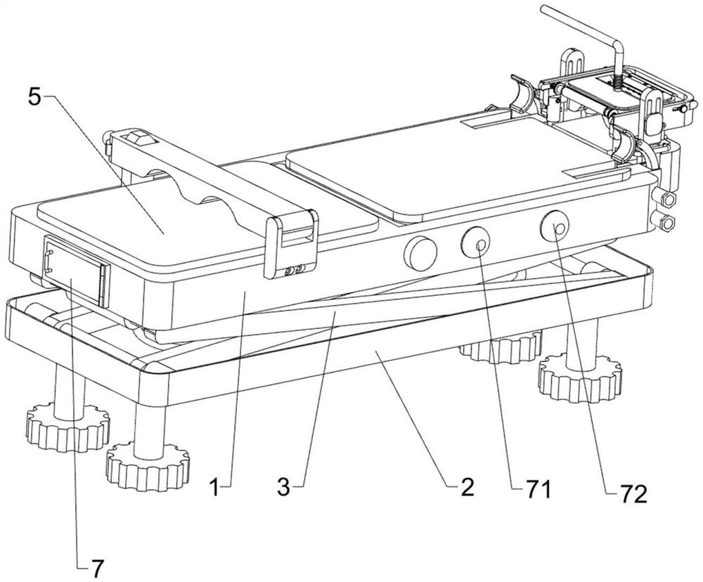
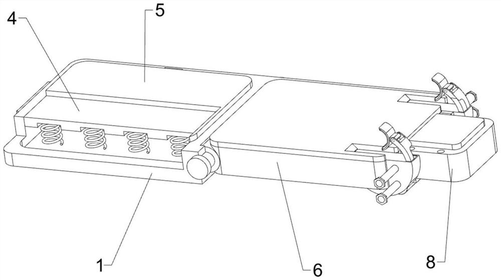
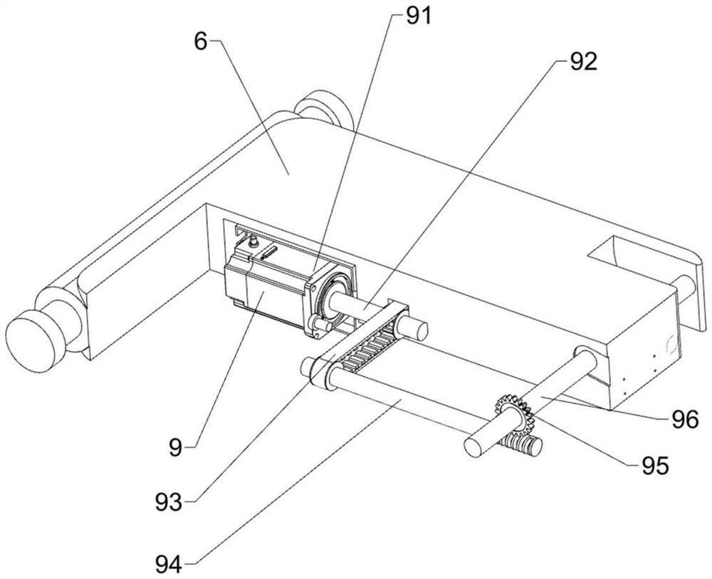
[0039] An assistive device for retinal surgery based on an optical coherent elastography system, such as Figure 1-Figure 5 As shown, it includes a supporting bed board 1, a positioning bottom frame 2, a buffer hinge frame 3, a shock-absorbing bed board 4, a sponge pad 5, a movable back board 6, a fixed button 71, a release button 72, a head support box 8, and a driving mechanism 9 And the limit mechanism 10, the upper sliding type of the positioning bottom frame 2 is provided with a buffer hinged frame 3, the upper part of the buffer hinged frame 3 is rotatably provided with a supporting bed board 1, and the inner side of the supporting bed board 1 is provided with a shock absorbing bed board 4 on the inner side of the supporting bed board 1 The right side rotating type is provided with movable backboard 6, the top of shock-absorbing bedboard 4 and the top of movable backboard 6 are all provided with sponge pad 5, the front right side of supporting bedboard 1 is provided with ...

Embodiment 2

[0044] On the basis of Example 1, such as Figure 6-Figure 13 As shown, a positioning mechanism 11 is also included, and the positioning mechanism 11 includes a first transmission assembly 111, a positioning short shaft 112, a column disc 113, a positioning bottom plate 114, a buffer guide column 115, a positioning frame 116, a rotating side plate 117, Positioning cylinder 118, positioning bracket 119, sponge positioning block 1110, limit frame 1111, breathing mask 1112, external oxygen tube 1113 and pressure sensor 1114, head support box 8 inside left rotating type is provided with positioning short axis 112, positioning A first transmission assembly 111 is arranged between the short shaft 112 and the middle part of the transmission cross bar 96. The first transmission assembly 111 is composed of two pulleys and a belt. The middle part of the positioning short shaft 112 and the middle part of the transmission cross bar 96 are provided with a pulley , a belt is wound between t...

Embodiment 3

[0049] On the basis of Example 2, such as Figure 14-Figure 17 As shown, an eye calibration mechanism 13 is also included, and the eye calibration mechanism 13 includes a movable frame 131, a locking bolt 132, a directional screw sleeve 133, a fixing knob 134, a positioning button 135 and a positioning light ring 136, and the front and rear of the limit frame 1111 Both sides are provided with movable frame 131, and movable frame 131 is all connected with positioning frame 116 in a sliding manner, and the right part of movable frame 131 outside is all threadedly provided with locking bolt 132, and locking bolt 132 cooperates with positioning frame 116, and movable frame 131 left side There are directional screw sleeves 133 between them, and the limit frame 1111 is slidingly connected with the directional screw sleeves 133. The front and back symmetrical threads on the directional screw sleeves 133 are provided with fixed knobs 134, and the fixed knobs 134 cooperate with the limi...


PUM


Abstract

The invention relates to a retina operation auxiliary device, in particular to a retina operation auxiliary device based on an optical coherence elastic imaging system. The technical problem to be solved is to provide the retina operation auxiliary device based on the optical coherence elastic imaging system, which can automatically open eyelids of a patient and can fix the body of the patient. The retina operation auxiliary device based on the optical coherence elastic imaging system comprises a supporting bed board, a positioning bottom frame, a buffering hinge frame, a damping bed board, a sponge mat and the like, the buffering hinge frame is arranged on the upper portion of the positioning bottom frame in a sliding mode, and the supporting bed board is rotationally arranged on the upper portion of the buffering hinge frame, a damping bed plate is arranged inside the supporting bed plate. Through cooperation of the driving mechanism and the limiting mechanism, the shoulder of a patient can be fixed, medical staff can conveniently conduct a cornea operation on the patient, and the situation that the operation is affected due to movement of the upper body of the patient is avoided.

Description

technical field [0001] The invention relates to an auxiliary device for retinal surgery, in particular to an auxiliary device for retinal surgery based on an optical coherent elastic imaging system. Background technique [0002] Elastic imaging technology is a technology that takes elastic parameters such as Young's modulus, shear modulus, stress and strain of soft tissue as the imaging object. With the development of optical coherence tomography, optical coherent elastography has , real-time image processing and non-invasive imaging are favored by doctors. [0003] At present, the most widely used clinical imaging techniques for measuring tissue elasticity are ultrasound and nuclear magnetic resonance imaging. Ophthalmology patients in the hospital can use nuclear magnetic resonance to detect the eyes. If an eye disease is detected, it is possible Retinal surgery is required for treatment. During the retinal surgery, the doctor will use tweezers to lift the patient's eyeli...

Claims


Application Information

Patent Timeline
Patent Type & Authority Applications(China)
IPC IPC(8): A61F9/007A61B3/12A61B17/02A61B90/14A61F5/37A61F9/00
CPCA61F9/007A61B3/1225A61B17/0231A61B90/14A61F5/3769A61F2009/0035
Inventor 黄国富赵雁之
Owner 黄国富
Why Eureka
Try Eureka