
High-temperature waste gas washing device and implementation method thereof

A technology of high-temperature waste gas and washing device, which is applied in separation methods, chemical instruments and methods, gaseous discharge wastewater treatment, etc., can solve the problems of increasing the difficulty of sewage treatment, increasing the amount of sewage generated, and losing the carrier of thermal energy, avoiding the need for The effect of dust adhering to the surface of the heat exchanger, avoiding heat exchange failure, and avoiding heat exchange deterioration

Pending Publication Date: 2021-10-22
李洪荣
View PDF4 Cites 1 Cited by
  • Summary
  • Abstract
  • Description
  • Claims
  • Application Information

AI Technical Summary

Problems solved by technology

[0003] In the prior art, the dedusting process of washing and spraying the exhaust gas is usually sprayed with normal temperature water to wash out the dust in the exhaust gas. In this way, because the dust washing process is lower than the temperature of the exhaust gas, the heat energy of the exhaust gas will be reduced. The heat is exchanged into the washing water, and the low temperature causes the water vapor in the exhaust gas to condense, which further loses the carrier of heat energy. What is more serious is that the exhaust gas washing process of the prior art not only consumes a large amount of water, but also because of the condensed water It will condense, which will further increase the amount of sewage generated after dust cleaning, which will increase the difficulty of subsequent sewage treatment, and almost make it impossible to clean the exhaust gas according to the standard requirements.

Method used

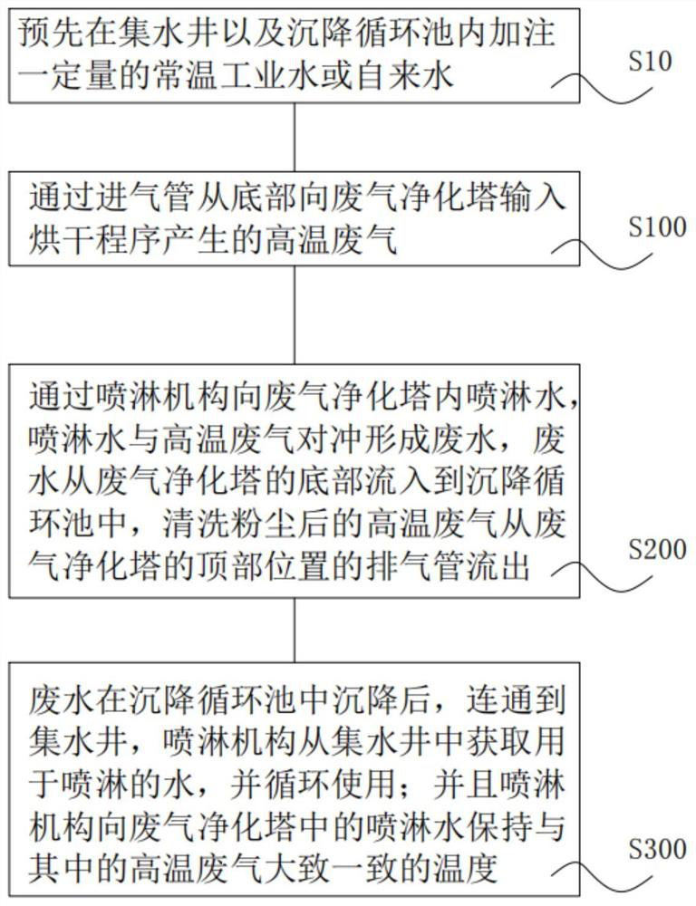

Image

  • High-temperature waste gas washing device and implementation method thereof
  • High-temperature waste gas washing device and implementation method thereof
  • High-temperature waste gas washing device and implementation method thereof

Examples


Embodiment Construction

[0053] In order to make the object, technical solution and advantages of the present invention more clear and definite, the present invention will be further described in detail below with reference to the accompanying drawings and examples. It should be understood that the specific embodiments described here are only used to explain the present invention, not to limit the present invention.

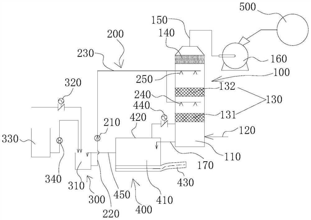
[0054] Based on the problems existing in the prior art, this embodiment provides a high-temperature exhaust gas washing device for washing high-temperature exhaust gas after drying, specifically as figure 1 As shown in , the high-temperature exhaust gas cleaning device in this embodiment includes: an exhaust gas purification tower 100, a spray mechanism 200 arranged on the exhaust gas purification tower 100, a water collection well 300 communicated with the spray mechanism 200, and a water well 300 connected to the exhaust gas purification tower 100. The settling circulation tank 400 con...

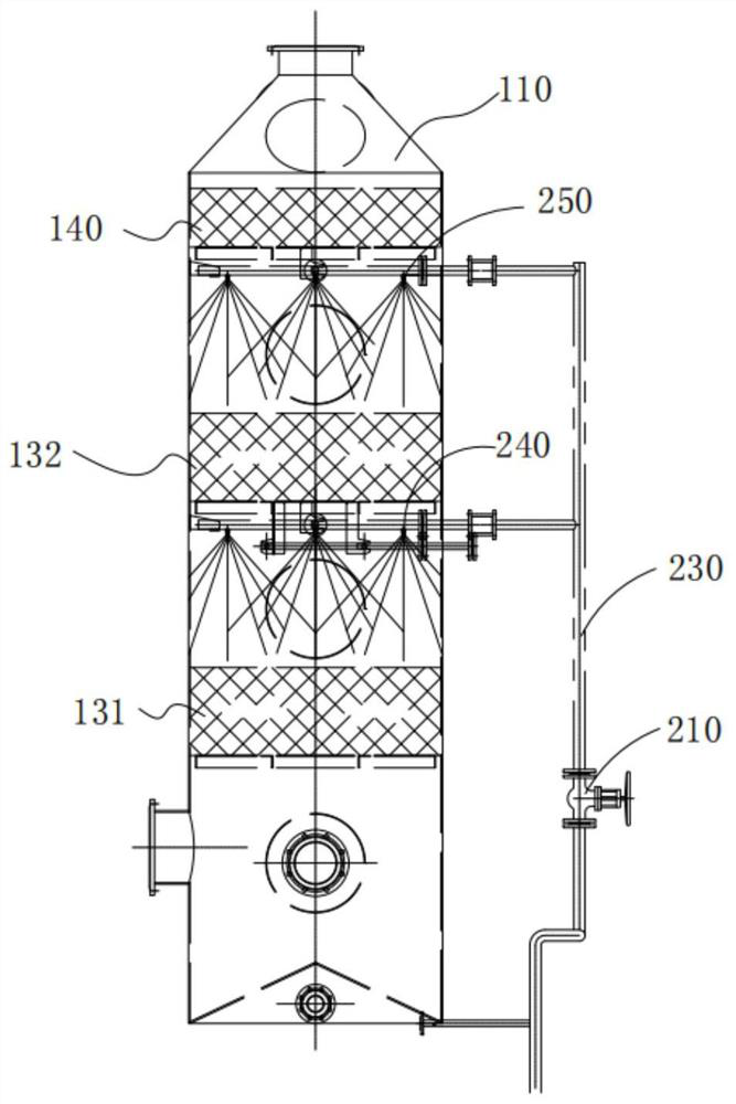

PUM


Abstract

The invention relates to a high-temperature waste gas washing device and an implementation method thereof. The high-temperature waste gas washing device comprises a waste gas purification tower, a spraying mechanism arranged on the waste gas purification tower, a water collecting well communicated with the spraying mechanism, and a sedimentation circulation pool communicated with the waste gas purification tower, and the sedimentation circulation pool is communicated with the water collecting well. The waste gas purification tower, the spraying mechanism, the water collecting well and the sedimentation circulation pool form a heat preservation water circulation system, on one hand, sprayed water of the spraying mechanism is kept at the temperature roughly the same as that of high-temperature waste gas, the sprayed water can be heated through an external heat source when necessary, on the other hand, the high-temperature waste gas is washed through the high-temperature water of the spraying mechanism, dust in the high-temperature waste gas can be washed out through the high-temperature water, a large amount of gasification latent heat is still reserved in the high-temperature waste gas, conditions are created for subsequent waste gas heat recovery, and meanwhile a large amount of condensation waste water can be prevented from being generated in the high-temperature waste gas washing process.

Description

technical field [0001] The invention relates to the technical field of high-temperature exhaust gas washing, in particular to an improvement of a high-temperature exhaust gas washing device and its implementation method. Background technique [0002] In the waste treatment industry, especially the drying industry (including the treatment of sludge, wood, fruits and vegetables, industrial waste residues, etc.), while drying the waste, a large amount of waste gas (the waste gas) generated in the drying process will be produced It is not dry, but the waste gas rich in water vapor is produced during the drying process), and the composition of the dried waste gas is complex, including air, water vapor, dust and trace volatile organic gases, etc. Among them, water vapor contains a large amount of latent heat of vaporization, which is basically close to the energy consumed in the drying process. If this heat is to be recovered, heat exchange is required, but since the exhaust gas ...

Claims


Application Information

Patent Timeline
Patent Type & Authority Applications(China)
IPC IPC(8): B01D47/14C02F1/52C02F103/18
CPCB01D47/14C02F1/52C02F2103/18Y02P70/10
Inventor 李洪荣
Owner 李洪荣
Learn More