Photovoltaic solder strip tin plating device of low-temperature halogen-free and lead-free soldering tin bar and welding method of photovoltaic solder strip tin plating device
A technology of lead-free solder and photovoltaic ribbon, applied in auxiliary devices, heating devices, welding equipment, etc., can solve problems affecting the production process, generating slag, affecting cutting, etc., to reduce workload, improve effect, and improve efficiency Effect
- Summary
- Abstract
- Description
- Claims
- Application Information
AI Technical Summary
Problems solved by technology
Method used
Image
Examples
Embodiment 1
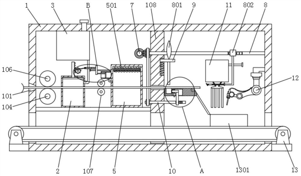
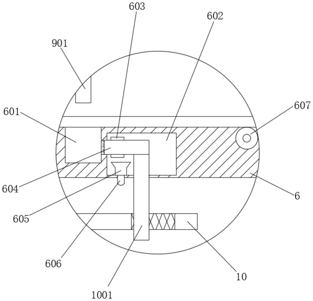
[0037] refer to Figure 1-6 , a photovoltaic ribbon tin coating device for low-temperature halogen-free lead-free solder strips, including a box body 1, and also includes: an input port 101, which is arranged on the side wall of the box body 1, and is used for copper strips to enter the box body 1; intermittent drive components , set in the box body 1, used to drive the copper strip to move intermittently, and fully tin-coat the copper strip; the tin coating box 2 and the liquid storage box 3 are all connected in the box body 1; the automatic liquid replenishment mechanism is set in the tin coating box 2 and the storage box Between the liquid tanks 3, wherein, the tin coating tank 2 is provided with a floating plate 201 matched with the automatic liquid replenishment mechanism; the cutting assembly is arranged in the tank body 1, and is used to cut the tin-coated copper strip into solderable solder The support plate 6 is connected in the box body 1, wherein the support plate 6...
Embodiment 2
[0041] refer to figure 1 , Figure 5 with Image 6 , is basically the same as Embodiment 1, furthermore, in order to make the copper strip move intermittently, the copper strip is fully tinned, the intermittent drive assembly includes a motor 102, a half gear 103, a first connecting shaft 104, a first gear 105 and The second connection shaft 106, the motor 102 is fixedly connected to the side wall of the casing 1, the output end of the motor 102 is connected with a drive shaft, the half gear 103 is fixedly connected to the drive shaft, the first connection shaft 104 and the second connection shaft 106 are both Rotationally connected in the box body 1, the first gear 105 is fixedly connected on the first connecting shaft 104, the half gear 103 is meshed with the first gear 105, and the first connecting shaft 104 and the second connecting shaft 106 are connected with a first The pulley set, the first connecting shaft 104 and the second connecting shaft 106 are fixedly connecte...
Embodiment 3
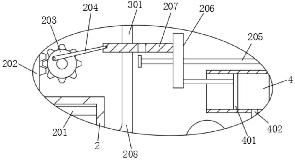
[0044] refer to figure 1 with image 3 , is basically the same as Embodiment 2, and furthermore, in order to automatically replenish the tin coating liquid, the automatic liquid replenishment mechanism includes a second gear 203, a rotating rod 204, a long rod 205, a slide plate 206 and a drawing plate 207, and the second gear 203 rotates Connected in the box body 1, the top of the floating plate 201 is fixedly connected with the rack plate 202 matched with the second gear 203, the long bar 205 is fixedly connected in the box body 1, the slide plate 206 is slidably connected on the long bar 205, and the The pull plate 207 is fixedly connected with the slide plate 206, the rotating rod 204 is rotatably connected between the second gear 203 and the pull plate 207, the bottom of the liquid storage tank 3 is connected with a drain pipe 301, and the side wall of the tin coating box 2 is connected with a liquid replenishment pipe 208 , the drawing plate 207 is slidably connected be...
PUM
 Abstract
Description
Claims
Application Information
 - R&D Engineer
- R&D Manager
- IP Professional
- Industry Leading Data Capabilities
- Powerful AI technology
- Patent DNA Extraction
Browse by: Latest US Patents, China's latest patents, Technical Efficacy Thesaurus, Application Domain, Technology Topic, Popular Technical Reports.
© 2024 PatSnap. All rights reserved.Legal|Privacy policy|Modern Slavery Act Transparency Statement|Sitemap|About US| Contact US: help@patsnap.com


