Constant pressure control valve of large-flow high-pressure plunger pump

A high-pressure plunger pump, constant pressure control technology, applied in the direction of fluid pressure actuating device, servo motor assembly, mechanical equipment, etc., can solve the problems of large external size of control valve, unsatisfactory control valve regulation ability, etc., to achieve compact shape , The spring adjustment force is small, the effect of reducing the cross-sectional area

CN113530906APending Publication Date: 2021-10-22宁波恒力液压股份有限公司
0 Cites 0 Cited by

Patent Information

Authority / Receiving Office
CN · China
Patent Type
Applications(China)
Current Assignee / Owner
Publication Date
2021-10-22

Smart Images

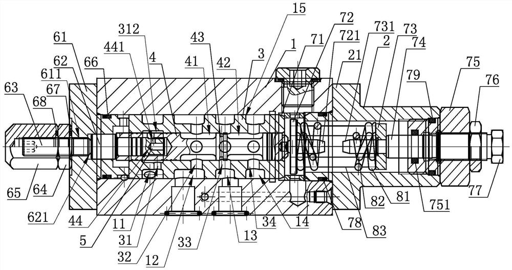
  • Figure 1
    Figure 1
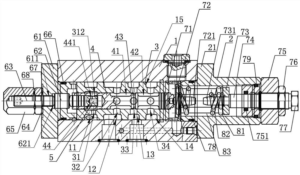
  • Figure 2
    Figure 2
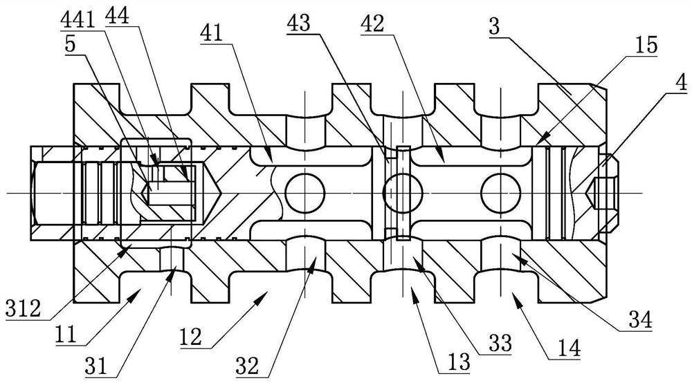
  • Figure 3
    Figure 3
Patent Text Reader

Abstract

The invention discloses a constant pressure control valve of a large-flow high-pressure plunger pump. The constant pressure control valve is characterized by comprising a valve body, a mounting base, a valve element assembly, a limiting ejector rod assembly and a pressure adjusting spring assembly, wherein a main body of the pressure adjusting spring assembly is located in the mounting base; the valve element assembly comprises a transition valve sleeve, a main sliding valve element and an inner valve element. The constant pressure control valve has the advantages that by increasing the diameter of the valve body, the diameter of the main sliding valve element in the valve body is increased, so that the response speed of the high-pressure plunger pump is increased; the inner valve element is placed in the main sliding valve element, so that the axial thrust of the main sliding valve element under the high-pressure working condition can be reduced, and the control force of the pressure adjusting spring assembly is reduced; when the diameter of the main sliding valve element is increased, the thrust for pushing the main sliding valve element can be kept unchanged by reducing the sectional area of the inner valve element, so that the adjusting force of a spring is small, and the appearance of the pressure adjusting spring assembly is compact; and when the set pressure needs to be remotely controlled and adjusted, remote pressure control over pressure oil introduced into the pressure adjusting spring assembly can be achieved only by disassembling the inner valve element in the valve element assembly.
Need to check novelty before this filing date? Find Prior Art

Description

technical field

[0001] The invention relates to a control valve device, in particular to a constant pressure control valve of a high-flow high-pressure plunger pump. Background technique

[0002] With the development of domestic large-scale equipment, the demand for axial piston pumps to develop to high pressure and large flow is accelerating, and the application of high-pressure piston pumps with a displacement of 500 ml and above per revolution is increasing. This requires upgrading the variable control method of the high-pressure plunger pump to improve the output flow control accuracy and real-time response capability of the high-pressure plunger pump. At the same time, taking into account the indicators such as easy and reliable operation, energy saving, and noise, it meets the needs of high-end hydraulic machinery supporting hydraulic systems. High pressure plunger pump requirements.

[0003] The conventional variable control methods of high-pressure plunger pumps are...

Examples

Embodiment Construction

[0020] The present invention will be further described in detail below in conjunction with the accompanying drawings and embodiments.

[0021]As shown in the figure, a constant pressure control valve of a high-flow high-pressure plunger pump includes a valve body 1, a mounting seat 2, a valve core assembly, a limit ejector rod assembly, and a pressure regulating spring assembly whose main body is located in the mounting seat 2. The mounting seat 2 is fixedly connected to the front end of the valve body 1, and the front end of the limit ejector rod assembly is fixedly connected to the rear end of the valve body 1. The valve body 1 is radially opened with a first channel 11 and a second channel 12 from back to front. , the third passage 13 and the leakage passage 14, the first passage 11 and the second passage 12 communicate with the outlet of the high-pressure plunger pump, the third passage 13 communicates with the large chamber of the variable cylinder, and the valve body 1 is...