
Monitoring system based on carbon fiber optical fiber composite rod and monitoring data interpretation method

An optical fiber composite and monitoring system technology, which is applied to measurement devices, earth-moving drilling, and optical devices to transmit sensing components, etc., can solve problems such as inability to meet, limited monitoring functions of oil production systems, etc., to improve production efficiency, easy to arrange, The effect of simplifying the layout process

Pending Publication Date: 2021-10-22
CHINA UNIV OF PETROLEUM (EAST CHINA) +1
View PDF6 Cites 0 Cited by
  • Summary
  • Abstract
  • Description
  • Claims
  • Application Information

AI Technical Summary

Problems solved by technology

However, the composite material coiled tubing intelligent oil recovery system can only test the temperature and pressure distribution of the wellbore. By analyzing the temperature change, it can be judged whether wax deposition occurs in the pipe, the wax deposition area and the location range, and the gas buried in the outer protective layer can be made to flow through a certain current. The internal cable heats up to remove wax, and the existing oil production system has limited monitoring functions, which cannot meet the requirements of monitoring multiple parameters such as fluid flow in the wellbore, water content, oil well pump working status, wellbore sand production status, wellbore wax deposition, and wellbore scaling. Unable to provide comprehensive data support for dynamic intelligent management and scientific decision-making of downhole production

Method used


Image

  • Monitoring system based on carbon fiber optical fiber composite rod and monitoring data interpretation method
  • Monitoring system based on carbon fiber optical fiber composite rod and monitoring data interpretation method
  • Monitoring system based on carbon fiber optical fiber composite rod and monitoring data interpretation method

Examples


Embodiment 1

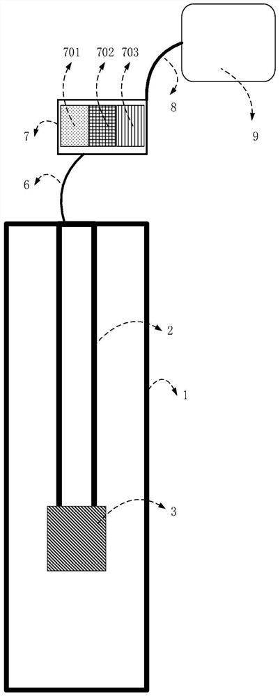
[0071] Such as figure 1 As shown, the monitoring system based on carbon fiber optic composite rod includes multifunctional carbon fiber optic composite rod 2, oil well pump 3, ground optical fiber monitoring signal acquisition system 7 and computer analysis system 9 for optical fiber monitoring data processing and interpretation.

[0072] The oil well pump 3 is connected to the bottom end of the multifunctional carbon fiber optical fiber composite rod 2 and lowered into the wellbore 1 .

[0073] The ground optical fiber monitoring signal acquisition system 7 is connected to the top of the multifunctional carbon fiber optical fiber composite rod 2 through the ground optical cable 6, and the optical fiber monitoring data processing and interpretation computer analysis system 9 is connected to the ground optical fiber monitoring signal acquisition system 7 through the ground data communication cable 8 connected.

[0074]The ground optical fiber monitoring signal acquisition syst...

Embodiment 2

[0095] This embodiment is a method for interpreting the wellbore production status monitoring data of a single oil layer pumping well. The monitoring system based on the carbon fiber optical fiber composite rod described in Embodiment 1 is used as an example to comprehensively interpret the downhole production dynamics, and the monitoring involved in the present invention The data interpretation method is described in detail, and the specific steps are as follows:

[0096] 1) The oil well pump 3 is started to discharge liquid, and the sound wave information, temperature information and pressure information generated when the fluid in the wellbore 1 flows are collected in real time through the multifunctional carbon fiber optical fiber composite rod 2 .

[0097] 2) Interpretation method for monitoring data of fluid flow and water cut in single-layer pumping wells: In order to reduce the ambiguity of fluid flow and water cut, it is necessary to perform multi-parameter fusion inte...

Embodiment 3

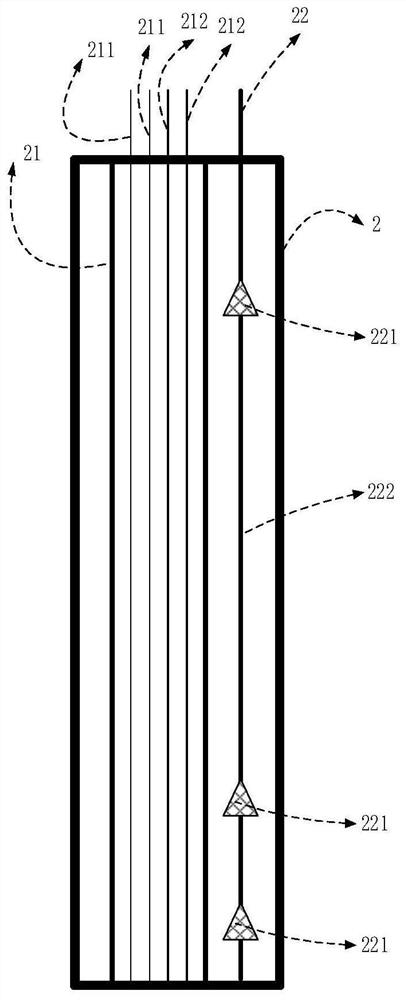
[0113] Different from Embodiment 2, this embodiment is a monitoring data interpretation method for fluid flow interpretation of multi-layer pumping wells. The difference from Embodiment 2 is that the depth range between two adjacent oil layers is required Inside, at least one fiber grating pressure gauge 221 is arranged at a corresponding position in the multifunctional carbon fiber optical fiber composite rod 2 .

[0114] Because a single oil layer is produced, the fluid flow in the entire wellbore 1 remains constant. When multiple oil layers are produced, the flow rate increases gradually from bottom to top, and the temperature and pressure between each oil layer are different, so at least one fiber grating needs to be arranged The pressure gauge 221 measures the pressure and temperature data between two adjacent oil layers.


PUM


Abstract

The invention belongs to the technical field of oil and gas exploitation, and particularly relates to a monitoring system based on a carbon fiber optical fiber composite rod and a monitoring data interpretation method. According to the monitoring system based on the carbon fiber optical fiber composite rod, distributed optical fiber temperature monitoring, distributed optical fiber sound wave monitoring and single-point optical fiber grating pressure monitoring are integrated, and simultaneous monitoring of multiple parameters such as underground temperature, pressure and sound waves is achieved; the requirements on dynamic real-time monitoring of underground production in high-temperature, high-pressure and corrosive environments are met. The invention further discloses a shaft production state monitoring data interpretation method which can obtain the fluid flow, the water content, the oil well pump working state, the shaft sand outlet position, the shaft wax precipitation position and the shaft scaling position information in the shaft according to the temperature information, the sound wave information and the pressure information collected in the shaft. Accurate data support is provided for dynamic intelligent management and scientific decision-making of underground production.

Description

technical field [0001] The invention belongs to the technical field of oil and gas exploitation, and in particular relates to a monitoring system based on a carbon fiber optical fiber composite rod and a monitoring data interpretation method. Background technique [0002] In recent years, the development of technologies such as optical fiber sensing and intelligent computing has promoted the development of intelligent oilfield construction. Through real-time downhole monitoring technology, wellbore equipment and fluid production dynamics can be obtained, which can provide real-time production decision-making basis for field engineers, thereby improving the level of oilfield operation and management. Distributed fiber optic temperature monitoring technology and distributed fiber optic acoustic wave monitoring technology, as one of the key technologies in the construction of intelligent oilfields, have received extensive attention from professionals in the oil and gas field an...

Claims


Application Information

Patent Timeline
Patent Type & Authority Applications(China)
IPC IPC(8): G01D21/02G01D5/26G01D5/353E21F17/18
CPCG01D21/02G01D5/268G01D5/353E21F17/18
Inventor 刘均荣王迪吕广平张锦杰
Owner CHINA UNIV OF PETROLEUM (EAST CHINA)
Learn More