
Jet afterburning compressed air energy storage system

A compressed air energy storage and energy storage system technology, which is applied to steam engine devices, mechanical equipment, pumps, etc., can solve problems such as high exhaust temperature, difficult processing, and limited ability to output electric energy externally

Pending Publication Date: 2021-10-29
ELECTRIC POWER RESEARCH INSTITUTE, CHINA SOUTHERN POWER GRID CO LTD +1
View PDF10 Cites 2 Cited by
  • Summary
  • Abstract
  • Description
  • Claims
  • Application Information

AI Technical Summary

Problems solved by technology

The non-supplementary combustion compressed air energy storage technology uses the compression heat generated by the compressor in the energy storage stage. Due to the low temperature of the compression heat and the low grade of heat, the energy storage system cannot fully perform the work of the high-pressure air in the power output stage. Release, the ability to output electric energy is limited
However, supplementary combustion compressed air energy storage systems in Germany and the United States need to customize natural gas burners with high pressure and high temperature parameters, which is difficult to process, and the inlet air temperature of the expander in the work stage of the energy storage system is high, and the temperature of the exhaust gas is also high. , leading to a large exhaust heat loss and reducing the efficiency of the energy storage system

Method used


Image

  • Jet afterburning compressed air energy storage system
  • Jet afterburning compressed air energy storage system
  • Jet afterburning compressed air energy storage system

Examples


Embodiment 1

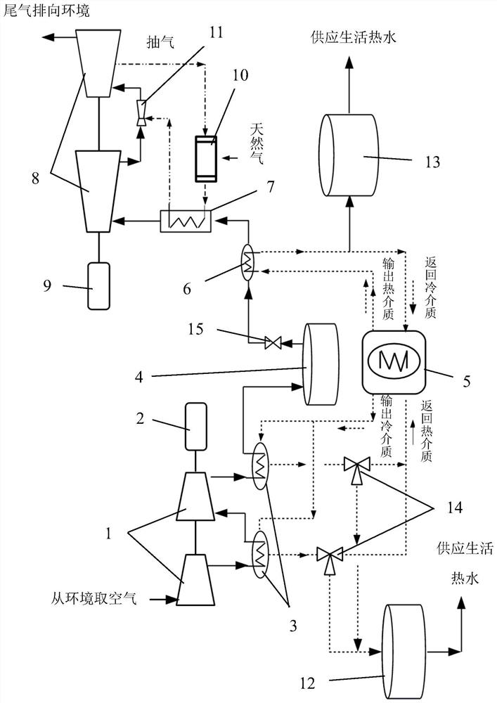
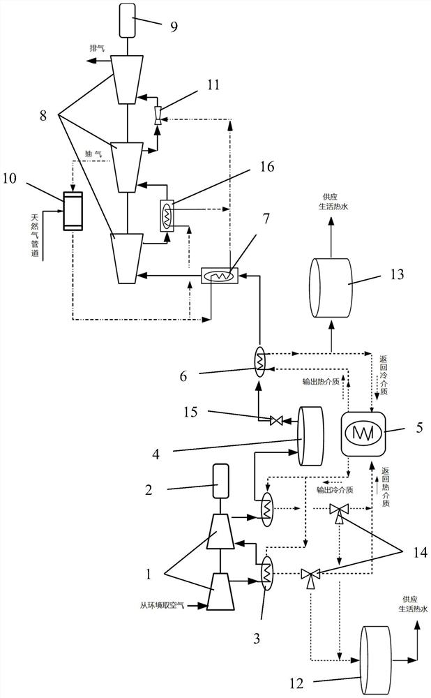
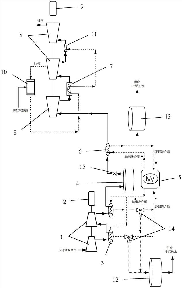
[0047] The above is the first embodiment of an injection post-combustion compressed air energy storage system provided by the embodiment of the present application, and the following is the second embodiment of an injection post-combustion compressed air energy storage system provided by the embodiment of the present application. For details, please refer to Figure 1 to Figure 4 .

[0048] The post-combustion compressed air energy storage system in this embodiment includes: an energy storage system, an electric energy release system and a compression heat storage device, both the energy storage system and the electric energy release system are connected to the compression heat storage device, and the electric energy release system includes a first inverter A heat exchanger 6, a second heat exchanger 7, a plurality of expanders 8 connected in series along the gas flow direction, a generator 9 connected to the expanders 8, a burner and an injector 11, the first heat exchanger 6 ...


PUM


Abstract

The invention discloses a jet afterburning compressed air energy storage system. The system comprises an energy storage system, an electric energy release system and a compression heat storage device. The energy storage system and the electric energy release system are both connected with the compression heat storage device; the electric energy release system comprises a first heat exchanger, a second heat exchanger, a plurality of expansion machines, a generator, a combustor and an ejector; the first heat exchanger is connected with the second heat exchanger or the first expansion machine; an air inlet of the combustor is connected with any one expansion machine; a gas outlet of the combustor is connected with the second heat exchanger; and any two adjacent expansion machines are connected through the ejector. A pressure flue gas outlet end of the second heat exchanger is connected with the ejector. According to the system, the utilization advantage of the domestic non-afterburning compressed air energy storage technology on compression heat is fully absorbed, on the basis of utilizing the compression heat, natural gas combustion is properly carried out, the power capability of high-pressure air in the expansion machines is improved, and the efficiency and the electric energy output capability of the energy storage system are effectively improved.

Description

technical field [0001] The present application relates to the technical field of electric energy storage, and in particular to an injection supplementary combustion compressed air energy storage system. Background technique [0002] With the development of the times, new energy power generation such as wind power and photovoltaic power generation will become an important source of electric energy in the power system. Due to the volatility and intermittent nature of new energy power generation such as wind power and photovoltaic power generation, it will bring great harm to the safe and stable operation of the power system. Here comes the challenge, so energy storage technology is essential. [0003] Electrochemical energy storage and compressed air energy storage technologies are the two most typical energy storage technologies, and both will have a wide range of application scenarios in the future new power system. The service life of the electrochemical energy storage sys...

Claims


Application Information

Patent Timeline
IPC IPC(8): F01K7/02F01K13/00F01K17/02F01K27/00F04B37/12F04B41/02F01D15/10
CPCF01K7/02F01K27/00F01K17/02F04B41/02F04B37/12F01D15/10F01K13/00Y02E60/16
Inventor 郭祚刚袁智勇谈竹奎雷金勇徐敏文贤馗
Owner ELECTRIC POWER RESEARCH INSTITUTE, CHINA SOUTHERN POWER GRID CO LTD
Learn More