Supercharge Your Innovation With Domain-Expert AI Agents!

Novel finned coil pipe

A fin coil and fin technology is applied in the field of thermal energy equipment, which can solve the problems of unbalanced heat absorption and heat exchange, large pitch of fin straight tubes, and compact volume of the body that cannot be heated, saving space and reducing welding. Joints, the effect of reducing the risk of water leakage

Pending Publication Date: 2021-10-29
克雷登热能设备(浙江)有限公司
View PDF0 Cites 0 Cited by
  • Summary
  • Abstract
  • Description
  • Claims
  • Application Information

AI Technical Summary

Problems solved by technology

[0002] The existing finned coils are generally serpentine or cylindrical, and the serpentine finned coils have the following disadvantages: First, when multiple tubes are arranged side by side, it is easy to have uneven distribution of water flow, resulting in uneven heat absorption and heat exchange, and there are Hidden danger of bias current overheating; Second, due to the limitation of the bending radius of the serpentine finned tube, the pitch between the straight finned tubes is relatively large, which cannot make the volume of the heating surface body more compact
The cylindrical finned coil is only suitable for the cylindrical heat exchange structure along the winding axial direction, which requires a certain height for the main body of the heat exchange structure, and cannot be applied to the heat exchange of the planar layer heat exchange structure.

Method used


Image

  • Novel finned coil pipe
  • Novel finned coil pipe
  • Novel finned coil pipe

Examples


Embodiment 1

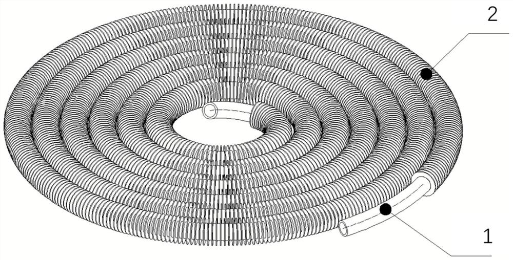
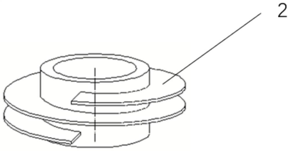
[0025] A new type of finned coil in this embodiment has a structure such as figure 1 As shown, it includes a base tube 1 and fins 2 spirally wound on the base tube 1 , and the base tube 1 and the fins 2 are integrally formed by laser welding. The base tube 1 is bent and coiled along a spiral to form a flat disk, and the fins 2 are as figure 2 The winding sheets shown are continuously helically wound on the outer wall of the base pipe 1, and then bent and coiled together with the base pipe 1 to form a plane disk shape. There are no fins 2 on both sides of the base pipe 1, which form the joints of the light pipe. During installation, only the joints at both ends of the base pipe 1 need to be connected to complete the installation of the coil, which reduces the number of welded joints and greatly reduces the Risk of water leakage.

[0026] After the base tube 1 is coiled, each circle of the base tube will stick to the base tube of its inner or outer ring, and the fins of the b...

Embodiment 2

[0030] A new type of fin coil in this embodiment differs from Embodiment 1 in that:

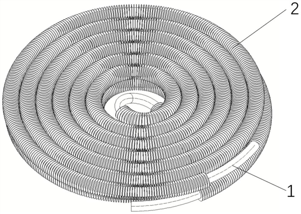
[0031] Its structure is as image 3 As shown, there are two base pipes 1, and the two layers of base pipes 1 are stacked up and down, and the joints in the middle are connected to each other to form a double-layer coil, and the upper and lower layers respectively have a joint at one end of the original base pipe. part, so that the internal heat exchange medium can flow in from one end of one base pipe and flow out from the other end joint of the other base pipe.

[0032] On the basis of this again, multi-layer base pipes can still be stacked, and only one of the joints needs to be connected with other base pipes in sequence to obtain a multi-layer coil with higher heat exchange capacity.

[0033] Other structures can refer to Embodiment 1.

Embodiment 3

[0035] A new type of fin coil in this embodiment differs from Embodiment 1 in that:

[0036] Fins such as Figure 4 As shown, there are continuous sawtooth-shaped gaps on its periphery, which can further improve the heat exchange capacity.

[0037] Other structures can have reference embodiment 1.


PUM

PropertyMeasurementUnit
Outer diameteraaaaaaaaaa
Thicknessaaaaaaaaaa
Thicknessaaaaaaaaaa

Abstract

The invention relates to a novel finned coil pipe. The novel finned coil pipe comprises base pipes and fins, wherein the base pipes are coiled into a planar disc shape along a spiral line, the fins are arranged on the outer walls of the base pipes, and no fin is arranged at the joint parts at the two ends of the base pipes. According to the novel finned coil pipe, the height of an energy saver or a heat exchanger can be conveniently reduced through the disc-shaped structure of the novel finned coil pipe, and more space is saved; and the novel finned coil pipe is formed by winding a whole fin steel pipe, joints are naturally formed at the two ends, welding joints are reduced, the water leakage risk is reduced, and a heating surface can be conveniently expanded through stacking.

Description

technical field [0001] The invention belongs to the field of heat energy equipment, and in particular relates to a novel fin coil. Background technique [0002] The existing finned coils are generally serpentine or cylindrical, and the serpentine finned coils have the following disadvantages: First, when multiple tubes are arranged side by side, it is easy to have uneven distribution of water flow, resulting in uneven heat absorption and heat exchange, and there are Hidden danger of overheating due to bias current; Second, due to the limitation of the bending radius of the elbow, the serpentine finned tube requires a relatively large pitch between the straight finned tubes, which cannot make the volume of the heating surface body more compact. The cylindrical finned coil is only suitable for the cylindrical heat exchange structure along the winding axial direction, which requires a certain height for the main body of the heat exchange structure, and cannot be applied to the ...

Claims


Application Information

Patent Timeline
IPC IPC(8): F28F1/36F28D7/04
CPCF28F1/36F28D7/04F28F2215/08
Inventor 杨斌黄坚徐宇张一飞金帮国
Owner 克雷登热能设备(浙江)有限公司
Features
  • R&D
  • Intellectual Property
  • Life Sciences
  • Materials
  • Tech Scout
  • Unparalleled Data Quality
  • Higher Quality Content
  • 60% Fewer Hallucinations
Learn More