Cleaning system and cleaning process for heat exchange module in air preheater

An air preheater and heat exchange module technology, applied in the field of cleaning systems, can solve the problems of labor-intensive drying, time-consuming drying, time-consuming and other problems, and achieve the effects of saving time and cost, improving cleaning efficiency, and shortening cleaning time

Pending Publication Date: 2021-10-29
王春卉 +1
View PDF0 Cites 1 Cited by
  • Summary
  • Abstract
  • Description
  • Claims
  • Application Information

AI Technical Summary

Problems solved by technology

Manual high-pressure water flushing includes: on-line flushing, that is, people enter the confined space of the air preheater device and use high-pressure water to flush the air preheater module. This flushing method has the advantages of fast time and less manpower, but its flushing effect is difficult to guarantee , and drying is time-consuming; off-line washing means that after the heat exchange module is transported out, the heat exchange module is disassembled and the heat exchange plates are washed one by one with water. This washing method has a relatively clean and thorough washing effect and does not affect the flue environment, but it is time-consuming , labor-intensive and time-consuming to dry
[0005] Under the background of the above fault conditions and treatment process, if the declogging treatment after the air preheater is blocked is not completely thorough, and the drying is not completely thorough, it will accelerate the cycle of blockage in the later stage. For the air preheater after the shutdown The off-line cleaning of modules lacks a process technology that can quickly clean and dry them. The present invention can provide a cleaning system and cleaning process for heat exchange modules in an air preheater, which can realize off-line large-scale heat exchange modules. Quick cleaning, drying, and the flexibility to facilitate transportation and on-site assembly, the process operation can save water resources, human resources and time costs

Method used


Image

  • Cleaning system and cleaning process for heat exchange module in air preheater
  • Cleaning system and cleaning process for heat exchange module in air preheater
  • Cleaning system and cleaning process for heat exchange module in air preheater

Examples


Embodiment Construction

[0059] The present invention will be described in detail below in conjunction with examples. It should be noted that, in the case of no conflict, the embodiments of the present invention and the features in the embodiments can be combined with each other. For the convenience of description, if the words "up", "down", "left" and "right" appear in the following, it only means that the directions of up, down, left and right are consistent with the drawings themselves, and do not limit the structure.

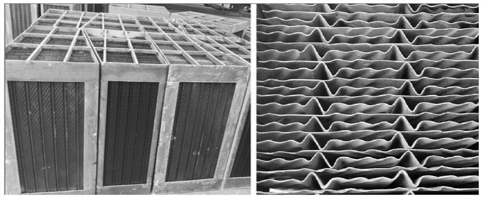
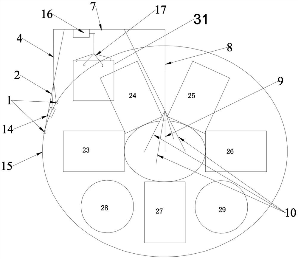
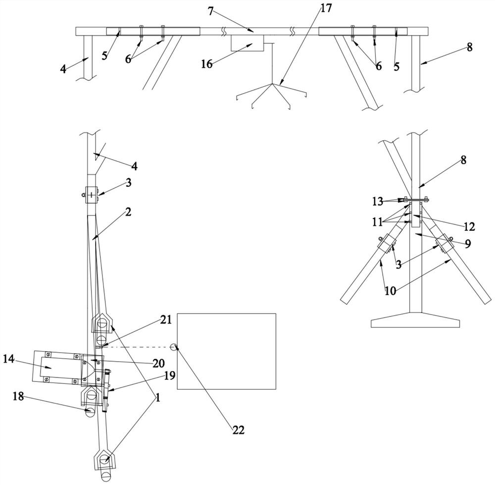
[0060] see Figure 2 to Figure 7 , a cleaning system for an air preheater, including a hanger, a central support 9, a softening cylinder 23, a first ultrasonic cleaning unit 24, a second ultrasonic cleaning unit 25, a purging unit 26 and a drying unit 27, the The softening cylinder 23, the first ultrasonic cleaning unit 24, the second ultrasonic cleaning unit 25, the purging unit 26 and the drying unit 27 are sequentially arranged around the central support 9;

[0061] The hanger ...


PUM


Abstract

The invention relates to a cleaning system and a cleaning process for a heat exchange module in an air preheater. The cleaning system comprises a hanging bracket, a center support, a softening cylinder, a first ultrasonic cleaning unit, a second ultrasonic cleaning unit, a purging unit and a drying unit, wherein the softening cylinder, the first ultrasonic cleaning unit, the second ultrasonic cleaning unit, the purging unit and the drying unit are sequentially arranged around the center support; the hanging bracket comprises a walking mechanism, a first support, a cross beam and a second support which are fixedly connected in sequence, and the lower end of the second support is rotationally connected with the central support, so that the hanging bracket can do circular motion in the horizontal plane around the central axis of the central support; the softening cylinder, the first ultrasonic cleaning unit, the second ultrasonic cleaning unit, the purging unit and the drying unit are all located between the walking mechanism and the center support; and a lifting mechanism is arranged on the cross beam. The cleaning system is compact in structure and small in occupied area, and the cleaning efficiency of the air preheater can be effectively improved.

Description

technical field [0001] The invention relates to a cleaning system and a cleaning process for a heat exchange module in an air preheater. Background technique [0002] Generally, an air preheater includes a plurality of heat exchange modules, and the heat exchange modules are usually formed by neatly arranging corrugated steel plates in a fixed steel frame. For details, see figure 1 . Taking the single-side rotary air preheater of a 600MW unit as an example, it includes three layers of heat exchange layers: upper, middle, and lower. The lower layer of cold end heat exchange layer contains 288 heat exchange modules with a height of about 1000mm. A single heat exchange module The corrugated steel plates with a thickness of 0.75-1.05mm are neatly arranged in the fixed steel frame, and the mutual interval is 0-10mm. [0003] Generally, rotary air preheaters are commonly used in units above 300MW to recover and utilize waste heat from flue gas. 2 As well as the escape ammonia o...

Claims


Application Information

Patent Timeline
Patent Type & Authority Applications(China)
IPC IPC(8): F28G13/00F28G1/16F28G7/00F28G9/00F28G15/00F28G15/02F26B23/00F23L15/00
CPCF28G13/00F28G7/00F28G9/00F28G1/16F28G15/003F28G15/02F26B23/00F23L15/00Y02E20/34
Inventor 肖育军肖聪王春卉
Owner 王春卉
Why Eureka
Try Eureka