
Heat dissipation system for slurry pump

A heat dissipation system and slurry pump technology, applied to pumps, parts of pumping devices for elastic fluids, pump components, etc., can solve the problems of sound insulation protective covers, unfavorable cooling fans, poor air flow, etc.

Active Publication Date: 2021-11-02
SANLIAN PUMP IND CO LTD
View PDF8 Cites 0 Cited by
  • Summary
  • Abstract
  • Description
  • Claims
  • Application Information

AI Technical Summary

Problems solved by technology

[0003] Usually large-scale slurry pumps are equipped with cooling fans and sound-proof protective covers. The sound-proof protective cover is not only used to reduce the noise of the slurry pump when it is working, but also can play a role in ensuring the safety of the operator; however, due to the sound-proof protective cover The air flow is not good, so the soundproof protective cover is not conducive to the cooling effect of the cooling fan

Method used


Image

  • Heat dissipation system for slurry pump
  • Heat dissipation system for slurry pump
  • Heat dissipation system for slurry pump

Examples


Embodiment 1

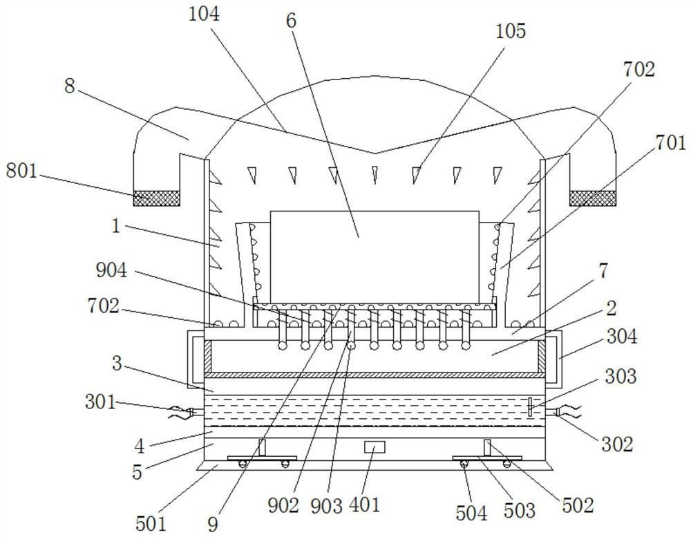
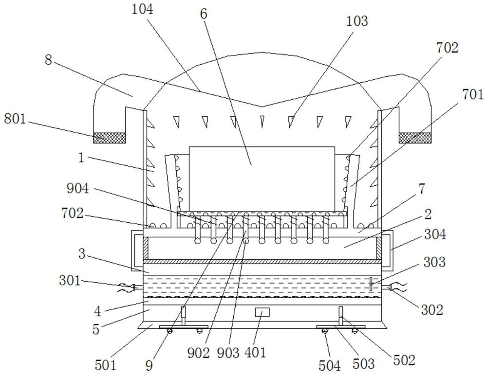
[0027] Embodiment 1: as Figure 1-6 As shown, a heat dissipation system of a slurry pump includes a base 5, an aeration pan 4 is fixedly installed on the top of the base 5, and a water cavity 3 is fixedly installed on the top of the aeration pan 4. The telescoping chamber 2 is fixedly installed on the top of the chamber 3 , the air chamber 7 is fixedly installed on the top of the telescopic chamber 2 , and the muffler cover 1 is fixedly installed on the top of the air chamber 7 .

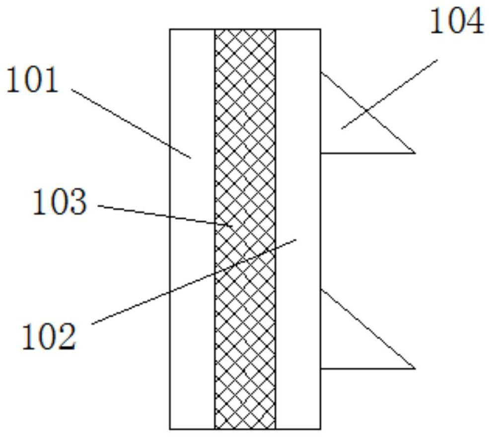
[0028] The sound-absorbing cover 1 is arranged in double layers, which are an outer cover 101 and an inner cover 102 respectively, and a sound-insulating cotton 103 is arranged between the outer cover 101 and the inner cover 102, and a plurality of sound-absorbing wedges 105 are fixedly connected to the inner wall of the sound-absorbing cover 1 A guide plate 104 is provided on the fixed side of the inner cavity of the sound-absorbing cover 1 .

[0029] The top side of the air cavity 7 is fixedly co...

Embodiment 2

[0039] Embodiment 2: as Figure 1-6 As shown, a heat dissipation system of a slurry pump includes a base 5, an aeration pan 4 is fixedly installed on the top of the base 5, and a water cavity 3 is fixedly installed on the top of the aeration pan 4. The telescoping chamber 2 is fixedly installed on the top of the chamber 3 , the air chamber 7 is fixedly installed on the top of the telescopic chamber 2 , and the muffler cover 1 is fixedly installed on the top of the air chamber 7 .

[0040] The sound-absorbing cover 1 is arranged in double layers, which are an outer cover 101 and an inner cover 102 respectively, and a sound-insulating cotton 103 is arranged between the outer cover 101 and the inner cover 102, and a plurality of sound-absorbing wedges 105 are fixedly connected to the inner wall of the sound-absorbing cover 1 A guide plate 104 is provided on the fixed side of the inner cavity of the sound-absorbing cover 1 .

[0041] The top side of the air cavity 7 is fixedly co...


PUM


Abstract

The invention discloses a heat dissipation system for a slurry pump. The heat dissipation system involves a base, wherein an aeration disc is fixedly installed at the top of the base, a water cavity is fixedly formed at the top of the aeration disc, an extendable cavity is fixedly formed at the top of the water cavity, an air cavity is fixedly formed at the top of the extendable cavity, and a silencing cover is fixedly installed at the top of the air cavity. The a heat dissipation system is simple in structure, and convenient and practical, and has the silencing function, the damping function and the cooling function.

Description

Technical field: [0001] The invention relates to the field of pumps, in particular to a cooling system for a slurry pump. Background technique: [0002] Slurry pumps belong to centrifugal pumps in terms of working principle. Conceptually, they refer to a kind of machinery that increases the energy of solid and liquid mixed media by means of centrifugal force (rotation of the impeller of the pump), and converts electrical energy into kinetic energy and Potential equipment. Mainly applicable to: mines, power plants, dredging, metallurgy, chemicals, building materials and petroleum industries. The name of the slurry pump is a kind of centrifugal pump divided from the perspective of conveying medium. In addition, the slurry pump can be divided into different types from different angles. In addition to pumping water, the water pump can also pump gas, solid, solid-liquid mixture - mineral powder mud! The power consumption of water pumps accounts for a large proportion of the c...

Claims


Application Information

Patent Timeline
Patent Type & Authority Applications(China)
IPC IPC(8): F04D29/58F04D29/66F04D7/04
CPCF04D29/586F04D29/669F04D7/04Y02W10/10
Inventor 孙国政张彦明王卫东杨荣东杨文琪
Owner SANLIAN PUMP IND CO LTD
Learn More