High-voltage power equipment connector heating defect emergency treatment device
A high-voltage power equipment, emergency treatment technology, applied in the direction of conductive connection, electrical component connection, circuit, etc., can solve the problem of high-voltage power equipment joint heating and other problems, achieve the effect of reducing switching operation, reducing current, and avoiding equipment burnout
- Summary
- Abstract
- Description
- Claims
- Application Information
AI Technical Summary
Problems solved by technology
Method used
Image
Examples
Embodiment 1
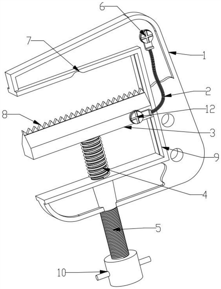
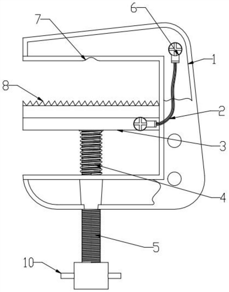
[0028] In this embodiment, an emergency treatment device for high-voltage power equipment joint heating defects, including a base 1, a movable splint 3, and a telescopic device 5, the bottom of the movable splint 3 is hinged to the telescopic device 5, and the base One side of 1 is provided with a shunt line 2, one end of the shunt line 2 is fixed to the base 1 and the other end is fixed to the movable splint 3, the C-shaped jaw formed by the movable splint 3 and the base 1, the shunt line One end of 2 is fixed to the base 1 through the first fixing screw 6, and the other end of the shunt line 2 is fixed to the movable splint 3 through the second fixing screw 12.
Embodiment 2
[0030] In this embodiment, in this embodiment, an emergency treatment device for heating defects of high-voltage power equipment joints, including a base 1, a movable splint 3, and a telescopic device 5, the bottom of the movable splint 3 is hinged to the telescopic device 5 One side of the base 1 is provided with a shunt line 2, one end of the shunt line 2 is fixed to the base 1 and the other end is fixed to the movable splint 3, and the C-shaped jaw formed by the movable splint 3 and the base 1 One end of the shunt line 2 is fixed to the base 1 through the first fixing screw 6 , and the other end of the shunt line 2 is fixed to the movable splint 3 through the second fixing screw 12 .
[0031] A guide block 11 is provided on the hinged side of the movable splint 3 and the base 1 , and a guide groove 9 is provided on the inner side of the base 1 , and the guide block 11 can slide freely in the guide groove 9 .
Embodiment 3
[0033] In this embodiment, an emergency treatment device for high-voltage power equipment joint heating defects, including a base 1, a movable splint 3, and a telescopic device 5, the bottom of the movable splint 3 is hinged to the telescopic device 5, and the base One side of 1 is provided with a shunt line 2, one end of the shunt line 2 is fixed to the base 1 and the other end is fixed to the movable splint 3, the C-shaped jaw formed by the movable splint 3 and the base 1, the shunt line One end of 2 is fixed to the base 1 through the first fixing screw 6, and the other end of the shunt line 2 is fixed to the movable splint 3 through the second fixing screw 12.
[0034] The hinged side of the movable splint 3 and the base 1 is provided with a guide block 11, and the inner side of the base 1 is provided with a guide groove 9, and the guide block 11 can slide freely in the guide groove 9. On the side of the base 1 opposite to the movable splint 3, there is a draw-in groove 7, ...
PUM
 Abstract
Description
Claims
Application Information
 - R&D
- Intellectual Property
- Life Sciences
- Materials
- Tech Scout
- Unparalleled Data Quality
- Higher Quality Content
- 60% Fewer Hallucinations
Browse by: Latest US Patents, China's latest patents, Technical Efficacy Thesaurus, Application Domain, Technology Topic, Popular Technical Reports.
© 2025 PatSnap. All rights reserved.Legal|Privacy policy|Modern Slavery Act Transparency Statement|Sitemap|About US| Contact US: help@patsnap.com


