Ultrasonic airflow cutting resistance reducing device for means of transportation

A vehicle and ultrasonic technology, which is applied in the field of flight resistance, sailing resistance component device, and driving resistance, can solve the problems affecting the driving speed of the vehicle, the energy consumption of the maximum stroke, and the difficulty of lifting, so as to achieve good shock absorption effect, The effect of improving driving range and convenient installation and application

Pending Publication Date: 2021-11-05
唐腊辉
View PDF0 Cites 0 Cited by
  • Summary
  • Abstract
  • Description
  • Claims
  • Application Information

AI Technical Summary

Problems solved by technology

Regardless of the aircraft flying in the sky, the vehicles traveling on land, or the aircraft navigating on water, in the process of flying, driving, and sailing, they are all subject to air resistance and air viscous package resistance to varying degrees at the same time, and when these The faster the vehicle travels, the greater the resistance it receives, which seriously affects the driving speed, maximum travel distance, driving energy consumption, etc. of these vehicles.
At present, in order to reduce the air resistance of these vehicles during driving, experts in the industry mainly focus on improving the aerodynamics of vehicles through continuous optimization, but it is very difficult to obtain the improvement

Method used


Image

  • Ultrasonic airflow cutting resistance reducing device for means of transportation
  • Ultrasonic airflow cutting resistance reducing device for means of transportation
  • Ultrasonic airflow cutting resistance reducing device for means of transportation

Examples


Embodiment Construction

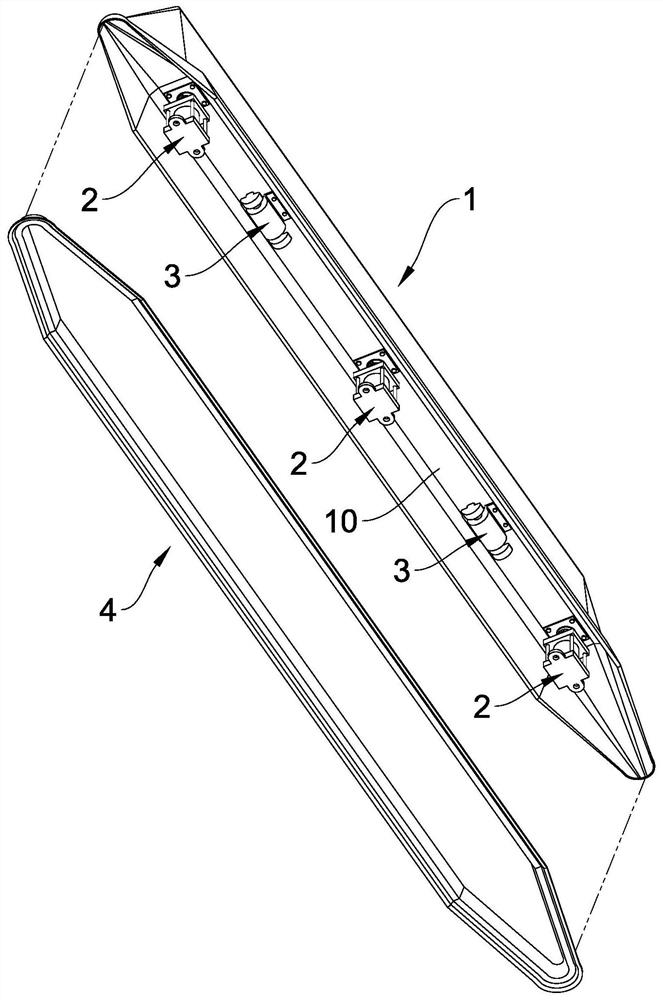
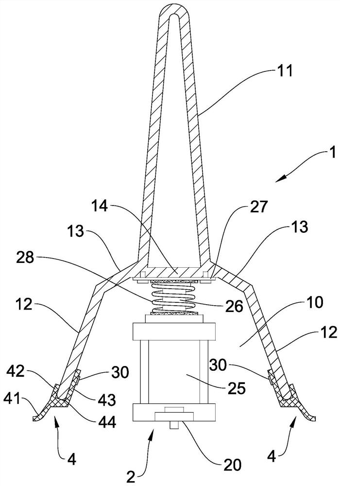
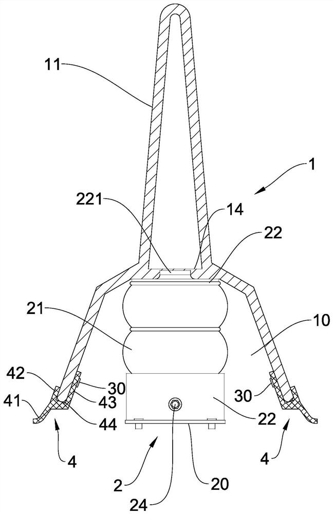
[0016] Such as Figure 1 to Figure 3 As shown, an ultrasonic airflow cutting drag reducing device for a vehicle comprises: an airflow cutting blade assembly 1, a shock absorbing installation assembly 2, an ultrasonic vibrating element 3, and a sealing rubber ring assembly 4; wherein, the airflow cutting blade assembly 1 It is an elongated piece with a narrow top and a wide bottom, and an accommodating cavity 10 is also provided on the bottom surface along its length direction. The top of the shock-absorbing mounting assembly 2 is fixedly connected to the inner cavity wall of the accommodation cavity 10, and a mounting and fixing bottom 20 is formed at the bottom of the shock-absorbing mounting assembly 2, and the mounting and fixing bottom 20 is used for connecting with the vehicle. Surface phase fixed installation, available as Figure 4 shown. Through the application of the shock-absorbing installation assembly, the ultrasonic vibrating element 3 of the present invention h...


PUM


Abstract

The invention relates to an ultrasonic airflow cutting resistance reducing device for means of transportation. The device comprises an airflow cutting blade assembly, a damping installation assembly, an ultrasonic vibration element and a sealing rubber ring assembly, the airflow cutting blade assembly is a long-strip-shaped sheet-shaped piece with the narrow upper portion and the wide lower portion, a containing cavity is further formed in the bottom face in the length direction of the airflow cutting blade assembly, the top end of the damping installation assembly is fixedly connected with the inner cavity wall of the containing cavity, an installation fixing bottom is formed at the bottom end of the damping installation assembly, the ultrasonic vibration element is installed on the inner cavity wall, and the sealing rubber ring assembly is installed on the airflow cutting blade assembly along the bottom edge of the periphery of the containing cavity. The ultrasonic vibration element is used for driving the airflow cutting blade assembly to make high-frequency ultrasonic vibration so as to cut, scatter and damage air resistance and air viscous wrapping resistance, so that the air resistance and air viscous friction resistance during forward driving of a vehicle are reduced, the driving speed of the vehicle is increased, the driving energy consumption is reduced, and the driving voyage is improved.

Description

technical field [0001] The invention relates to the field of vehicles, in particular to a component device installed on the vehicle for reducing the running resistance, flight resistance and sailing resistance of the vehicle. Background technique [0002] As we all know, the air has a certain humidity, and tens of thousands of extremely fine substances are entrained in the air. The humidity of the air and the substances entrained in the air make the air flow have a certain viscosity. Regardless of the aircraft flying in the sky, the vehicles traveling on land, or the aircraft navigating on water, in the process of flying, driving, and sailing, they are all subject to air resistance and air viscous package resistance to varying degrees at the same time, and when these The faster the vehicle travels, the greater the resistance it receives, which seriously affects the travel speed, maximum travel, and energy consumption of these vehicles. At present, in order to reduce the air...

Claims


Application Information

Patent Timeline
Patent Type & Authority Applications(China)
IPC IPC(8): B62D35/00B63B1/32B64C1/38F15D1/00F16F15/02F16F15/08F16F15/023F16F15/067
CPCB62D35/00B63B1/32B64C1/38F15D1/00F16F15/02F16F15/08F16F15/0232F16F15/023F16F15/067Y02T70/10Y02T10/82B64C23/005F15D1/007B61D17/02F15D1/12B62D35/005
Inventor 唐腊辉
Owner 唐腊辉
Why Eureka
Try Eureka