Pellet roasting system and method based on sintering machine

A sintering machine and pelletizing technology, applied in the field of pellet roasting, can solve the problems of poor cooling effect, large floor space and high cost, and achieve the effects of increasing production capacity, reducing floor space and reducing equipment cost

Active Publication Date: 2021-11-05
ZHONGYE-CHANGTIAN INT ENG CO LTD
View PDF4 Cites 2 Cited by
  • Summary
  • Abstract
  • Description
  • Claims
  • Application Information

AI Technical Summary

Problems solved by technology

[0006] Aiming at the problems of high cost, poor cooling effect and large occupied area in the prior art, the present invention proposes a pellet roasting system and method based on a sintering machine

Method used


Image

  • Pellet roasting system and method based on sintering machine
  • Pellet roasting system and method based on sintering machine
  • Pellet roasting system and method based on sintering machine

Examples


Embodiment 1

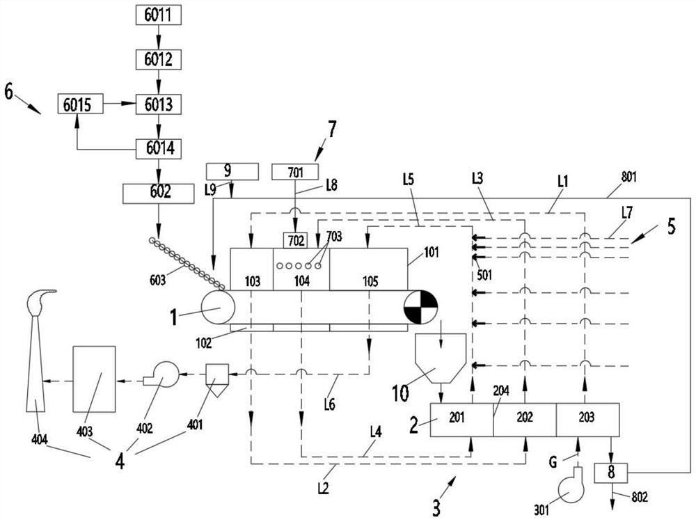
[0103] A pellet roasting system based on a sintering machine, the system includes: a sintering machine 1 , an annular cooler 2 , a circulating air flow unit 3 and a flue gas treatment unit 4 . The discharge port of the sintering machine 1 is connected with the feed port of the annular cooler 2 . The circulating air flow unit 3 is arranged between the sintering machine 1 , the annular cooler 2 and the flue gas treatment unit 4 . A fume hood 101 is arranged above the sintering machine 1 , and a wind box 102 is arranged below it. According to the direction of materials, the fume hood 101 located above the sintering machine 1 is divided into a preheating section 103 , a combustion section 104 and a roasting section 105 in sequence. The annular cooler 2 is sequentially divided into a first annular cooling section 201 , a second annular cooling section 202 and a third annular cooling section 203 . The wind boxes 102 located at the bottoms of the roasting section 105, the combustio...

Embodiment 2

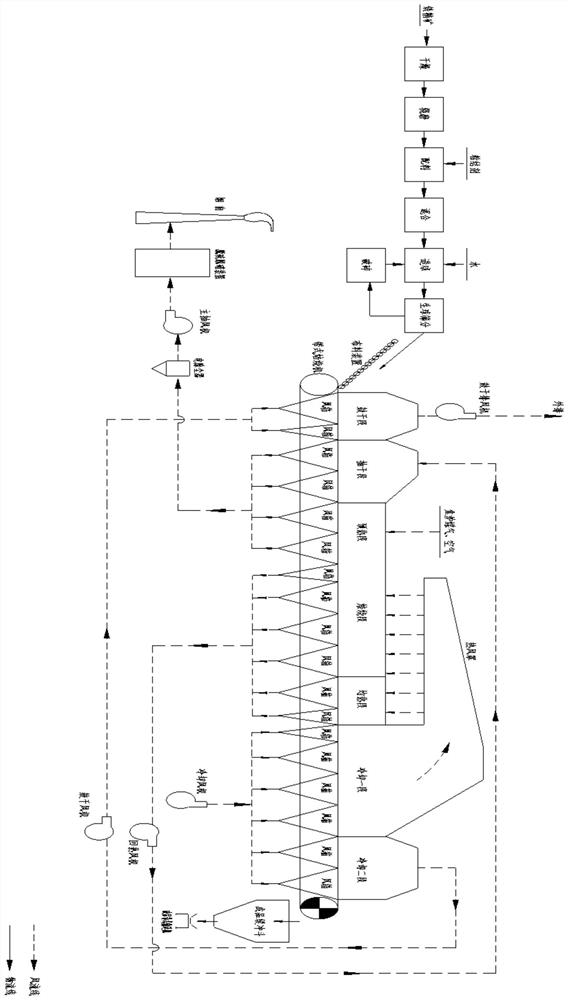
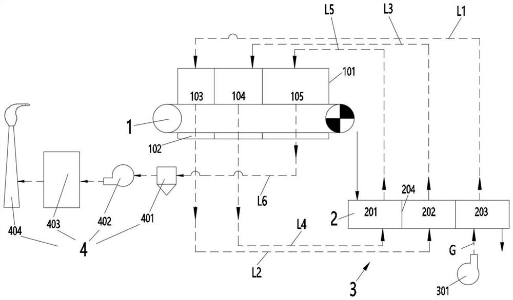
[0105] Such as figure 2 As shown, Embodiment 1 is repeated, except that the air circulation unit 3 includes a cooling fan 301 and a circulation pipeline. The circulation pipeline specifically includes: the cooling fan 301 communicates with the air inlet of the third ring cooling section 203 through the air inlet pipe G. The air outlet of the third ring cooling section 203 communicates with the air inlet of the preheating section 103 through the first gas pipeline L1. The air outlet of the preheating section 103 communicates with the air inlet of the second ring cooling section 202 through the second gas pipeline L2. The air outlet of the second ring cooling section 202 communicates with the air inlet of the combustion section 104 through the third gas pipeline L3. The air outlet of the combustion section 104 communicates with the air inlet of the ring cooling section 201 through the fourth gas pipeline L4. The air outlet of the annular cooling section 201 is connected with ...

Embodiment 3

[0107] Example 2 is repeated, except that the fifth gas pipeline L5 is provided with a supplementary heat device 5 . The heating device 5 includes a burner 501 and a gas delivery pipeline L7. The burner 501 is arranged in the fifth gas pipeline L5. The air inlet of the burner 501 communicates with the air outlet of the gas delivery pipeline L7.

[0108] The heating device 5 includes several burners 501 . The several burners 501 are all arranged in the fifth gas pipeline L5, and the several burners 501 are independently connected to the gas delivery pipeline L7. In the fifth gas pipeline L5, along the direction of the gas flow, the number of burners 501 is distributed in an increasing manner.


PUM

PropertyMeasurementUnit
specific surface areaaaaaaaaaaa
thicknessaaaaaaaaaa
thicknessaaaaaaaaaa

Abstract

The invention discloses a pellet roasting system based on a sintering machine. The system comprises the sintering machine, a circular cooler, a circulating air flow unit and a flue gas treatment unit. A discharge port of the sintering machine is connected with a feed port of the circular cooler. The circulating air flow unit is arranged among the sintering machine, the circular cooler and the flue gas treatment unit. A smoke hood is arranged above the sintering machine, and an air bellow is arranged below the sintering machine. According to the trend of materials, the smoke hood located above the sintering machine is sequentially divided into a preheating section, a combustion section and a roasting section. The sintering machine is adopted for pellet roasting, meanwhile, an air flow system is improved, the flue gas circulation heat utilization rate is increased, energy consumption is reduced, meanwhile, the roasting effect is improved, meanwhile, the good cooling effect can be achieved, generation of nitric oxide is reduced through gradient heat compensation, the desulfurization and denitrification cost is reduced, and the environment is protected.

Description

technical field [0001] The invention relates to a pellet roasting device and method, in particular to a pellet roasting system and method based on a sintering machine, belonging to the field of pellet roasting. Background technique [0002] Pelletizing is a method of artificial bulk raw materials, so that the physical properties and chemical composition of powdery materials can meet the requirements of the next step of processing. The pellet production process is a production process for extracting pellets, which is a common process for extracting iron ore in the iron and steel smelting industry. Pellets are finely ground iron concentrate powder or other iron-containing powders mixed with a small amount of additives, and then rolled into balls through a pelletizer under the condition of adding water and moistening, and then roasted to consolidate into a pellet with a certain strength and strength. Spherical ferrous raw materials with metallurgical properties. The main proc...

Claims


Application Information

Patent Timeline
Patent Type & Authority Applications(China)
IPC IPC(8): C22B1/22C22B1/24
CPCC22B1/22C22B1/2406
Inventor 李康谢朝明代友训王春林
Owner ZHONGYE-CHANGTIAN INT ENG CO LTD
Why Eureka
Try Eureka