
Detection device for motor shaft

A detection device, motor shaft technology, applied in the direction of measuring device, using sound wave/ultrasonic wave/infrasonic wave to analyze solids, using sound wave/ultrasonic wave/infrasonic wave to analyze materials, etc. It can solve the problems of insufficient shaft radius, failure, stress concentration, etc., and achieve The effect of improving usability

Active Publication Date: 2021-11-05
常州瀚宇电子有限公司
View PDF9 Cites 1 Cited by
  • Summary
  • Abstract
  • Description
  • Claims
  • Application Information

AI Technical Summary

Problems solved by technology

Unreasonable design will lead to insufficient shaft radius, and the stress concentration generated by the change of installation position may cause catastrophic failure of the shaft after a very short service life, so the shaft must meet certain technical requirements
[0003] Application number: 202020716461.X, name: a motor shaft detection device, which discloses the vibration of the motor shaft at different speeds driven by a servo motor; application number: 201910720405.5, name: a motor shaft detection device, which discloses Ultrasonic metal flaw detection, concentricity detection, workpiece size detection and workpiece weight detection are used for the motor shaft. From the perspective of the above two disclosed inventions, the main items of the vibration detection and metal flaw detection detection for the motor shaft are not reflected in the On the same detection equipment, and the second comparison file is a functional module accumulation, which fails to reflect the detection on the specific detection device mechanism

Method used


Image

  • Detection device for motor shaft
  • Detection device for motor shaft
  • Detection device for motor shaft

Examples


Embodiment

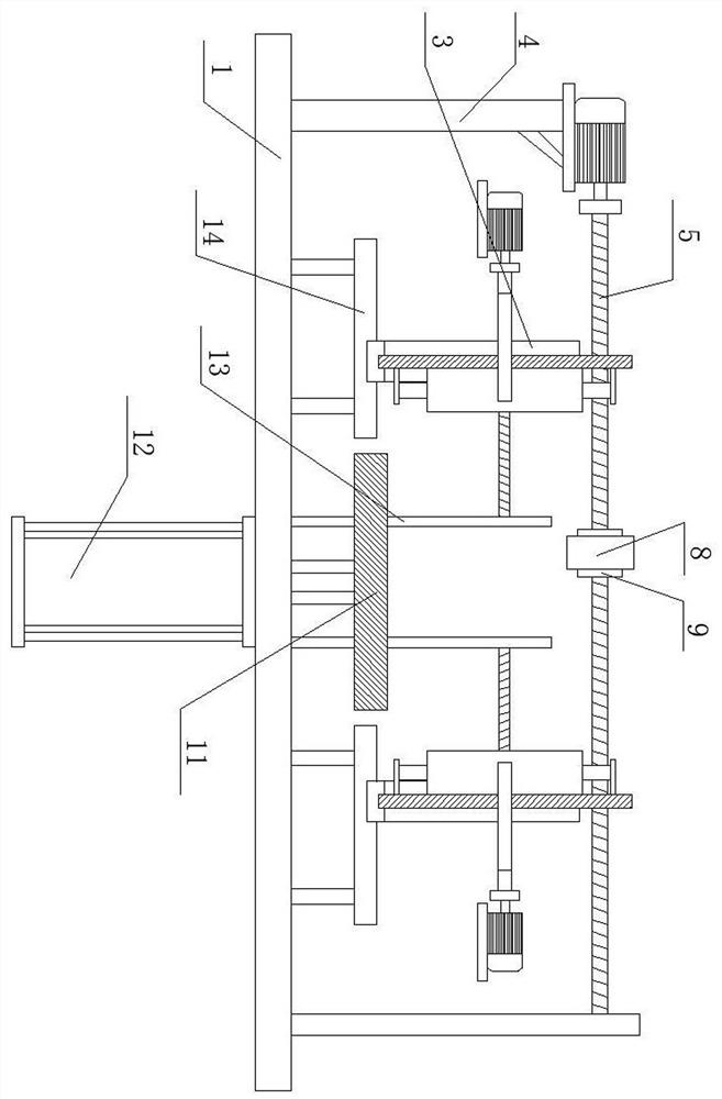
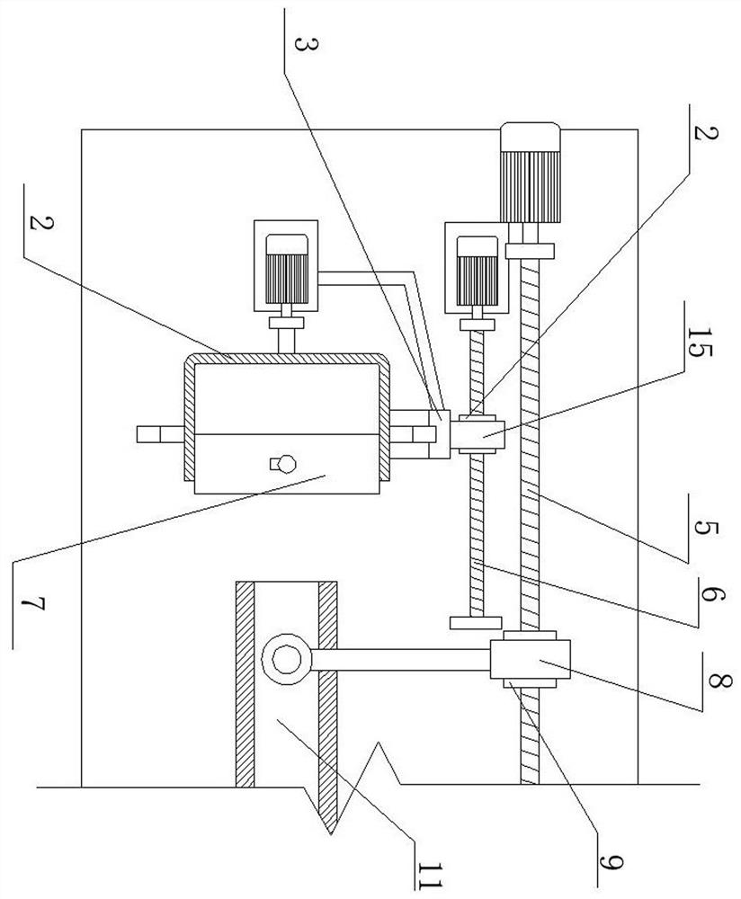
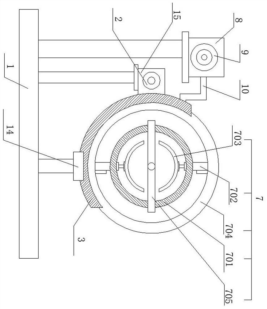
[0036] Example: refer to Figure 1-8 , a detection device for the motor shaft, including a detection workbench 1, a shaft support plate 11, a rotating clamping mechanism 7, an equipment rack 4, a transverse flaw detection mechanism, a moving mechanism and a torque sensor 19, and three groups are arranged above the detection workbench 1 The equipment frame 4 and the fixed plate 13 , and the transverse flaw detection mechanism and the moving mechanism are correspondingly arranged between the equipment frame 4 and the fixed plate 13 .

[0037] Further, the bottoms of the equipment frame 4 and the fixed plate 13 are bolted to the table top of the inspection table 1, and the cooperation between the equipment frame 4 and the fixed plate 13 plays the role of installation support for the setting of the transverse flaw detection mechanism and the moving mechanism.


PUM


Abstract

The invention relates to the technical field of motor accessory production equipment detection, and especially relates to a detection device for amotor shaft. The device comprises a detection workbench, a shaft supporting plate, a rotary clamping mechanism, equipment frames, a transverse flaw detection mechanism, a moving mechanism and a torque sensor. Three groups of equipment racks and fixing plates are arranged above the detection workbench, the transverse flaw detection mechanism and the moving mechanism are correspondingly arranged between the equipment frame and the fixing plate, the transverse flaw detection mechanism comprises a driving motor I, a first ball screw, a first connecting block, a first nut pair, a connecting rod and an ultrasonic flaw detector, and the driving motor I is fixedly connected with the first ball screw through a shaft coupling. According to the motor shaft detection device, through the arrangement of the detection device, the gyroscopic moment detection of the motor shaft and the nondestructive flaw detection of the motor shaft by using the ultrasonic detector are integrated in the same detection equipment, so that the use performance of the motor shaft detection device is improved.

Description

technical field [0001] The invention relates to the technical field of detection of motor accessory production equipment, in particular to a detection device for a motor shaft. Background technique [0002] The motor shaft is a cylindrical part protruding from the motor and its casing. The shaft is the main support and connection part of the armature part of the motor, and is also the output part of the power generated by the motor. The purpose of the shaft is to convert the energy of the motor into the final Purpose, the precision pin and the motor shaft are used to provide the speed and torque of the motor, which is one of the indispensable important parts in the motor. Simple shafts are commonly used in motor applications such as power steering control systems, small appliance motors, power tool motors and specialty components. Unreasonable design will lead to insufficient shaft radius, and the stress concentration generated by the change of installation position may cau...

Claims


Application Information

Patent Timeline
Patent Type & Authority Applications(China)
IPC IPC(8): G01D21/02G01L3/04G01N29/04G01N29/26
CPCG01D21/02G01L3/04G01N29/04G01N29/26
Inventor 史韶峰金少靖史寒雨
Owner 常州瀚宇电子有限公司
Learn More