
A new energy vehicle battery control circuit board packaging equipment

A technology for new energy vehicles and packaging equipment, applied in printed circuits, printed circuit manufacturing, printed circuit components, etc., can solve the problems of low packaging and testing efficiency, difficult production and application, and damaged circuit components, so as to reduce pollution and The risk of damage, guaranteed performance, and the effect of accelerating packaging efficiency

Active Publication Date: 2022-02-15
深圳市东瀛技术有限公司
View PDF0 Cites 0 Cited by
  • Summary
  • Abstract
  • Description
  • Claims
  • Application Information

AI Technical Summary

Problems solved by technology

In the existing battery control circuit board, in order to facilitate the installation and protection of the circuit board, the circuit board is generally installed in an electrical box for packaging, and with the improvement of the performance of the power battery, the circuit board It will generate a lot of heat. In order to dissipate heat, several cooling holes will be opened on the electrical box, but the cooling effect of the cooling holes is very limited, and the contact area between the circuit board and the electrical box is small, so it is difficult to use the electrical box. Heat transfer and heat dissipation, so the overall heat dissipation effect of the circuit board with this package structure is not good, which seriously affects the working performance of the circuit board during the working process
Moreover, the packaging of the existing battery control circuit boards mostly adopts manual packaging and testing. During the packaging and testing process, when the battery control circuit board is taken and placed by hand, there is a risk of contamination and damage to the circuit components, and the efficiency of packaging and testing is extremely high. Low, difficult to achieve large-scale production applications

Method used


Image

  • A new energy vehicle battery control circuit board packaging equipment
  • A new energy vehicle battery control circuit board packaging equipment
  • A new energy vehicle battery control circuit board packaging equipment

Examples


Embodiment

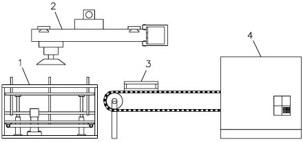
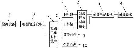
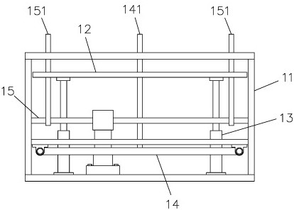
[0025] Such as Figure 1 to Figure 8 As shown, this embodiment discloses a packaging device for a new energy vehicle battery control circuit board, including a loading rack 1 for placing a circuit board to be packaged, and a loading rack 1 for picking and placing a circuit board to be packaged. Go to the packaging and conveying equipment 3 and take the packaged circuit board from the packaging and conveying equipment 3 to the packaging pick-and-discharge manipulator 2 of the unloading rack 5, which is used to transport the circuit board to be packaged into the packaging equipment 4 and package it. The encapsulation delivery equipment 3 that the circuit board is sent out from the encapsulation equipment 4, the encapsulation equipment 4 that is used to encapsulate the circuit board and the unloading rack 5 that is used to place the encapsulated circuit board, the material loading rack 1, the encapsulation conveyance The equipment 3 and the packaging equipment 4 are arranged hori...


PUM


Abstract

A packaging device for a new energy vehicle battery control circuit board, including a loading frame for placing the circuit board to be packaged, for taking the circuit board to be packaged from the loading The packaging pick-and-place manipulator that picks and puts the circuit board from the packaging and conveying equipment to the unloading rack, the packaging and conveying equipment that is used to transport the circuit board to be packaged into the packaging equipment and sends the packaged circuit board out of the packaging equipment, and is used for The packaging equipment for packaging the circuit board and the unloading rack for placing the packaged circuit board realize automatic loading, conveying, packaging and unloading through the use of automatic packaging equipment, and the packaging and conveying equipment reciprocates left and right, thus greatly The packaging efficiency of the circuit board is accelerated, and manual operation is not required in the whole process, which reduces the risk of contamination and damage to the circuit board.

Description

technical field [0001] The invention belongs to the technical field of new energy vehicles, and in particular relates to a packaging device for a battery control circuit board of a new energy vehicle. Background technique [0002] With the support of the country's continuous new energy policy, the key technologies of new energy vehicles in my country have made significant progress. Especially in new energy vehicle power battery technology, it is already at the leading level in the world. In terms of mileage, the data from the Ministry of Industry and Information Technology shows that the average mileage of pure electric passenger vehicles has increased from 253 kilometers in 2016 to 378 kilometers in 2020. At present, many cars have reached more than 500 kilometers, and the cruising range has been greatly improved on the original basis. With the continuous improvement of new energy vehicle battery technology, correspondingly, the control circuit board, which is the most imp...

Claims


Application Information

Patent Timeline
Patent Type & Authority Patents(China)
IPC IPC(8): H05K3/00H05K3/22H05K3/28H05K1/02H05K7/20B65G37/00B65G47/74B07C5/00B07C5/02B07C5/36B07C5/38
Inventor 黄丽娟
Owner 深圳市东瀛技术有限公司
Learn More