
Cantilever type counter-current chromatograph without adapter

A countercurrent chromatograph and cantilever technology, applied in instruments, scientific instruments, measuring devices, etc., can solve the problems of solvent leakage, easy damage, interference of test results, etc., and achieve simplified installation, easy disassembly and installation, and simple structure. Effect

Active Publication Date: 2021-11-09
SICHUAN UNIV
View PDF5 Cites 0 Cited by
  • Summary
  • Abstract
  • Description
  • Claims
  • Application Information

AI Technical Summary

Problems solved by technology

Under this structure, first, when the output pipe and the input pipe are respectively connected with the sampling pipe, an adapter needs to be installed. After the adapter fails, solvent leakage will occur at the connection of the pipeline, resulting in solvent loss and pollution; second, the adapter at the adapter The sealing interface is difficult to clean, resulting in a small amount of sample residue at the adapter, which interferes with the test results of other samples; third, in order to improve the separation efficiency of the countercurrent chromatograph, input tubes and output tubes with larger inner diameters are required. A larger uncoiled hose is required to wrap, but this will increase the mass and volume of the entire uncoiled hose, resulting in poor dynamic balance performance of the uncoiled tube at high speeds; Fourth, the uncoiled hose is a soft structure , frequently subjected to various stresses during the working process of the countercurrent chromatograph, which is prone to damage and reduces the stability and reliability of the system

Method used


Image

  • Cantilever type counter-current chromatograph without adapter
  • Cantilever type counter-current chromatograph without adapter
  • Cantilever type counter-current chromatograph without adapter

Examples


Embodiment Construction

[0026] In order to make the purpose, technical solution and advantages of the present invention more clear, the present invention will be further described in detail below in conjunction with the accompanying drawings and embodiments. It should be understood that the specific embodiments described here are only used to explain the present invention, and are not intended to limit the present invention, that is, the described embodiments are only some of the embodiments of the present invention, but not all of the embodiments. The components of the embodiments of the invention generally described and illustrated in the figures herein may be arranged and designed in a variety of different configurations.

[0027] Accordingly, the following detailed description of the embodiments of the invention provided in the accompanying drawings is not intended to limit the scope of the claimed invention, but merely represents selected embodiments of the invention. Based on the embodiments of...


PUM


Abstract

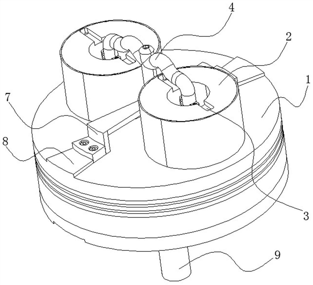
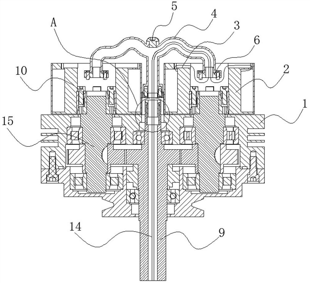
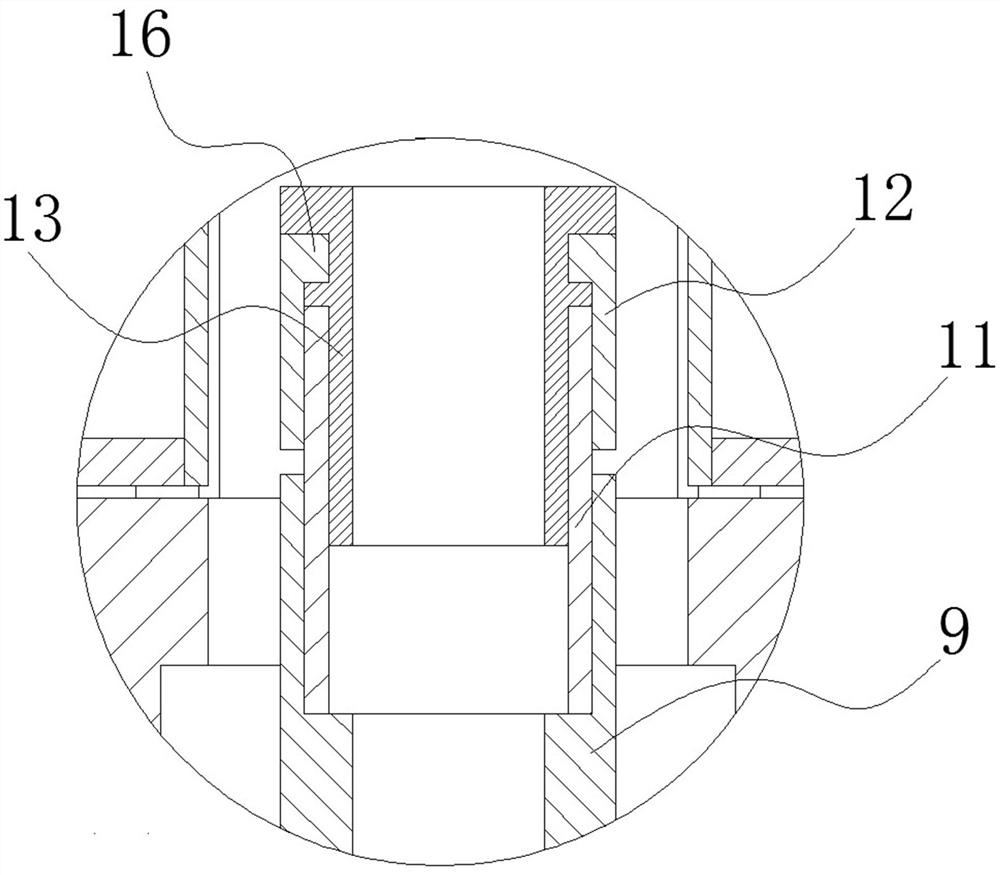
The invention relates to the technical field of counter-current chromatographs, and particularly discloses a cantilever type counter-current chromatograph without an adapter. Thecantilever type counter-current chromatograph comprises a planetary gear train and a separation column connected with a planetary gear shaft of the planetary gear train, and further comprises a connecting plate, a sampling tube and an integrally-formed hard unwinding frame fixed to the connecting plate. The connecting plate is fixed to a planet carrier of the planetary gear train, one end of the hard unwinding frame and a center shaft of the planetary gear train are coaxially arranged, the other end of the hard unwinding frame is located in the separation column and arranged in the center of the separation column in a suspended mode, the hard unwinding frame is of a hollow structure, and the middle of the sampling pipe is wound in the separation column; and the two ends of the sampling tube penetrate out of the hard unwinding frame and the central shaft in sequence. The cantilever type counter-current chromatograph has the advantages that the unwinding pipe is arranged into the hard unwinding frame of the integrated structure, the hard unwinding frame is fixedly connected to the planet carrier through the connecting plate, the two ends of the hard unwinding frame are suspended above the center shaft in the separation column, and adapter connection is not needed.

Description

technical field [0001] The invention relates to the technical field of countercurrent chromatographs, in particular to a cantilever type countercurrent chromatograph without an adapter. Background technique [0002] Countercurrent chromatography technology is a continuous and efficient liquid-liquid partition chromatography separation technology developed in the 1970s. It generates a two-dimensional force field through synchronous planetary motion of simultaneous revolution and rotation, and realizes separation during high-speed rotation. extraction. Since the countercurrent chromatograph is a continuous flow separation system, the pipeline runs through from the beginning to the end, and the separation column rotates at a high speed during the working process. In order to meet the above requirements, the countercurrent chromatograph needs to be unwound. The unwinding method is to unwind through the unwinding hose, that is, the two ends of the unwinding hose are respectively...

Claims


Application Information

Patent Timeline
IPC IPC(8): G01N30/42
CPCG01N30/42
Inventor 陈海军彭爱华
Owner SICHUAN UNIV
Learn More