Electric heating dipping and drying rotary kiln

An electric heating and rotary kiln technology, applied in lighting and heating equipment, rotary drum furnaces, sustainable manufacturing/processing, etc., can solve the problems of inability to meet catalyst drying requirements, too much liquid on catalyst surface area, and difficulty in catalyst withdrawal. Achieve the effect of avoiding unloading difficulties, avoiding unstable operation and uniform load

Pending Publication Date: 2021-11-12
CHENGDU ZHONGKE PURUI PURIFYING EQUIP
View PDF7 Cites 1 Cited by
  • Summary
  • Abstract
  • Description
  • Claims
  • Application Information

AI Technical Summary

Problems solved by technology

However, in the impregnation and drying tower, it takes a long time to drain after the impregnation process is completed, and the surface area of ​​the catalyst in the lower part of the tower is more liquid, and there are still more active components on the outer surface of the catalyst particles in the lower part of the tower after drying, and even active components The crystallization compaction makes it more difficult for the catalyst to be withdrawn from the impregnation drying tower
[0009] To sum up, the existing rotary kiln, drying tower, oven, microwave oven and other equipment cannot meet the drying requirements in the catalyst preparation process

Method used


Image

  • Electric heating dipping and drying rotary kiln
  • Electric heating dipping and drying rotary kiln
  • Electric heating dipping and drying rotary kiln

Examples


Embodiment 1

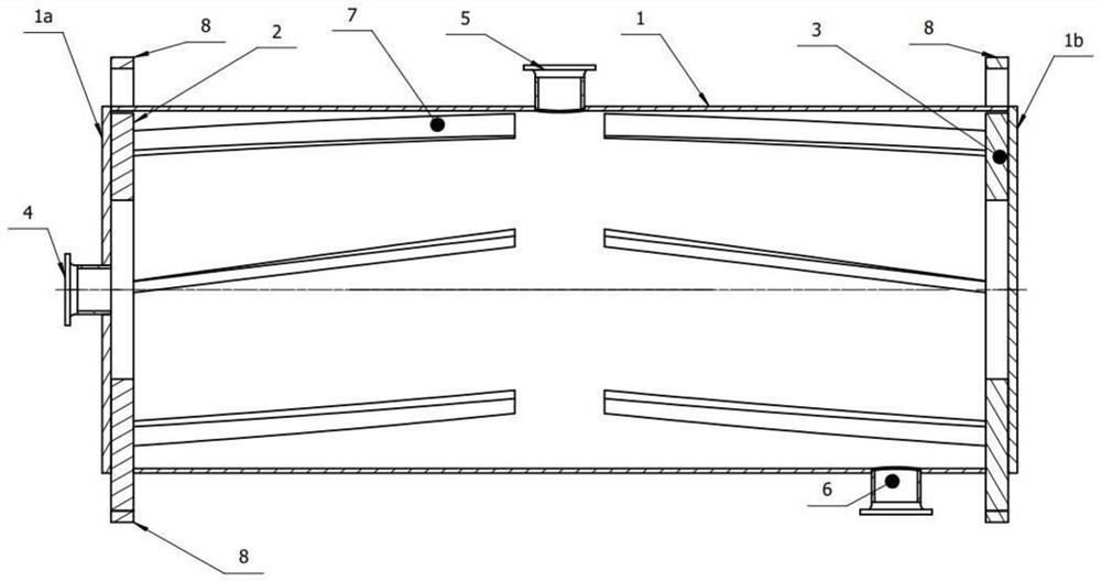
[0056] figure 1 Schematically shows the cross-sectional structure of an electric heating impregnation drying rotary kiln passing through the rotation axis of the rotary tube, such as figure 1 As shown, the rotary tube 1 is a cylinder with two end panels 1a and 1b at both ends, which is made of insulating material. The two ends of the rotary tube 1 are provided with a negative pole 2 and a positive pole 3. The positive and negative poles of the power supply pass through the wall of the rotary tube 1 and are electrically connected to the two conductive rings 8 outside the rotary tube 1. The two conductive rings 8 are further conductively connected to the positive and negative poles of the heating power supply through brushes respectively. A first nozzle 4 is opened on the cover plate of the rotary pipe end, and a second nozzle 5 and a third nozzle 6 are opened on the cylinder wall. A plurality of frying boards 7 are fixed on the inner wall of the rotary tube cylinder 1. When t...

Embodiment 2

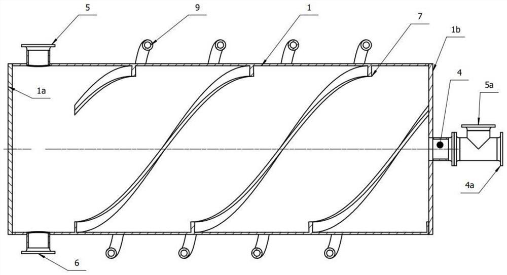
[0062] figure 2 It shows the cross-sectional structure of another electric heating impregnation drying rotary kiln passing through the rotation axis of the rotary tube. Such as figure 2 As shown, the difference from Embodiment 1 is that no electrodes are arranged inside the rotary tube 1 . The cylinder of the rotary tube is covered with an induction coil 9, and the coil is made of a copper tube, and the cylinder of the rotary tube 1 is made of an epoxy resin plate. When heating, a 1 kHz alternating current is applied at both ends of the coil 9, and an induced current is generated in the activated carbon carrier pile inside the rotary tube 1. The carrier pile has a certain resistance, thereby generating resistance heat to heat and dry the catalyst.

[0063] The entry and exit of solid, gas and liquid materials can be carried out in the manner described in Example 1. Since the inclination of the frying plate 7 in the present embodiment along the direction of the axis of rot...

Embodiment 3

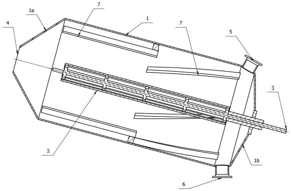
[0067] image 3 It shows the cross-sectional structure of another electric heating impregnation drying rotary kiln passing through the rotary axis of the rotary tube, such as image 3 As shown, the rotary tube 1 is made of metal material, and the included angle between its rotation axis and the horizontal plane is 15°. The positive pole 3 is mechanically sealed but electrically insulated with the rotary tube 1, and the rotary tube 1 is used as the negative pole of the power supply. The first nozzle 4 is used as the inlet of the solid material and the outlet of the gas phase, the third nozzle 6 is used as the outlet of the circulating immersion liquid, and the second nozzle 5 is used as the outlet of the solid material. When the solid material is unloaded, the second nozzle 5 rotates to the third nozzle 6 in the accompanying drawing. Because the inclination of the rotary pipe 1 is relatively large, it is easy to discharge the catalyst with good fluidity such as activated carbo...


PUM


Abstract

The invention discloses an electric heating dipping and drying rotary kiln, which is suitable for dipping and drying processes in a preparation process of a conductive catalyst, and is provided with a rotary pipe, a power supply positive electrode and a power supply negative electrode in the rotary pipe, and a solid material inlet, a solid material outlet, a gas phase outlet and a liquid phase material inlet and/or outlet on the rotary pipe. The power supply positive electrode and the power supply negative electrode in the rotary pipe are conductively connected with a heating power supply through electric brushes. A solid material between the power supply positive electrode and the power supply negative electrode is used as a resistor for heating and drying. The electric heating dipping and drying rotary kiln is also used as a dipping tank of a supported catalyst, and becomes dipping and drying integrated equipment. Compared with the prior art, the electric heating dipping and drying rotary kiln is high in heating speed and uniform in heating, catalyst active components are uniformly loaded in single catalyst carrier particles and among particles, and catalyst products are easy to discharge after drying is completed.

Description

technical field [0001] The invention relates to the technical field of chemical equipment, in particular to an electrically heated rotary kiln used for impregnation and drying processes in the catalyst preparation process. Background technique [0002] Rotary kiln is an important heating and calcination equipment in the chemical industry, materials, and pharmaceutical industries, and it is widely used. According to different industries, heating raw materials, heat sources, and heating methods, rotary kilns have different forms. However, it always has a swivel tube, which rotates about its axis of rotation during heating operation. There is a type of electric heating rotary kiln, which feeds current into the material to be heated, and uses the resistance heating of the conductive material itself to heat the material itself. The rotary kiln saves the heat transfer process from the heat source to the heated material, has high electric heating efficiency, compact equipment, an...

Claims


Application Information

Patent Timeline
Patent Type & Authority Applications(China)
IPC IPC(8): F27B7/10F27B7/16F27B7/20F27B7/22F27B7/34
CPCF27B7/16F27B7/34F27B7/22F27B7/20F27B7/10Y02P20/10
Inventor 冯良荣
Owner CHENGDU ZHONGKE PURUI PURIFYING EQUIP
Why Eureka
Try Eureka