A monitoring method and device for gas emission

A technology for monitoring equipment and gas emissions, applied to the analysis of gas mixtures, measuring devices, instruments, etc., can solve the problems of unorganized emissions failing to meet emission standards, surrounding pollution, waste of resources, etc., to avoid differences in air components at fixed points, The effect of reducing manufacturing costs and reducing processing costs

Active Publication Date: 2021-12-24
江苏嘉斌环保科技有限公司
View PDF6 Cites 0 Cited by
  • Summary
  • Abstract
  • Description
  • Claims
  • Application Information

AI Technical Summary

Problems solved by technology

Toxic and harmful gases that are discharged in an organized manner through the exhaust stack can be treated through recovery and combustion treatment facilities, while unorganized emissions that fail to meet the emission standards are also an important reason for industrial enterprises to pollute the surrounding area.
The existing equipment is to detect the exhaust source, but some pollutants can be purified through the atmospheric environment, and excessive requirements will easily lead to waste of resources

Method used


Image

  • A monitoring method and device for gas emission
  • A monitoring method and device for gas emission
  • A monitoring method and device for gas emission

Examples


Embodiment 1

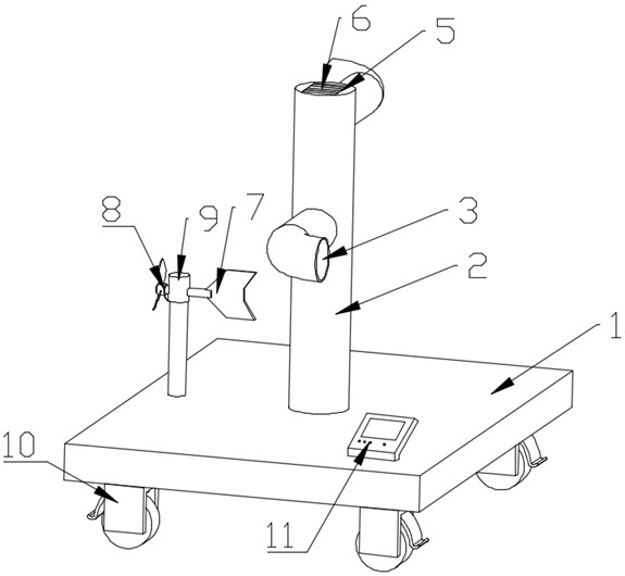
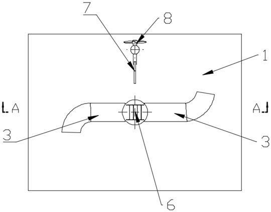
[0037] refer to Figure 1~Figure 3 , in this embodiment, a monitoring device for gas discharge is proposed, which is used to monitor the discharge of polluted gas. The monitoring device for gas discharge includes: a base 1, a rotating barrel 2, a wind power fan blade 8, Wind deflector 7, gas monitor 15 and controller 11.

[0038] The base 1 forms the main body of the installation. The base 1 can be a plate-shaped structure or a bracket structure. The base 1 can be fixed at a designated place through the base 1, or the base 1 can be moved to a designated place. The designated place can pollute the gas emission source Set the circumference for the center of the circle. refer to Figure 5 , so that the circumference monitoring can be carried out. The bottom of the base 1 is provided with a rotating wheel, a universal wheel 10 or a combination of the rotating wheel and the universal wheel 10, and the rotating wheel or the universal wheel 10 facilitates the movement of the devic...

Embodiment 2

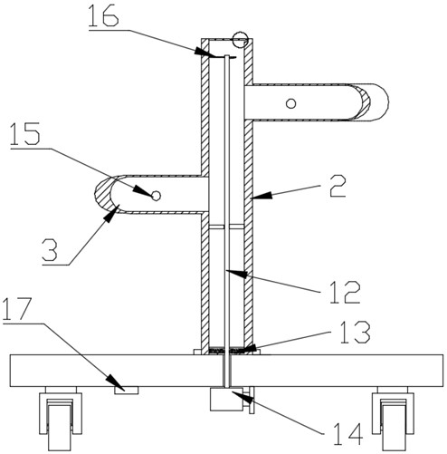
[0044] The interior of the rotating barrel 2 is provided with a gas drive device, which drives the gas so that the gas can enter the inside of the intake pipe 3 for monitoring. The gas drive device includes a rotating shaft 12, a motor 14 and an exhaust The fan blade 16, the rotation shaft 12 is arranged in the inside of the rotating barrel 2, the motor 14 is installed on the base 1, the rotation shaft 12 is connected with an exhaust fan blade 16, the exhaust fan blade 16 is located above the intake pipe 3, and Under the action of the motor 14, the rotating shaft 12 rotates, and the rotating shaft 12 drives the exhaust fan blade 16 to rotate to drive the air flow, which avoids large errors in the monitoring of free air diffusion. The rotating barrel 2 is rotatably connected to the base 1, and the rotating shaft 12 and the rotating barrel 2 are transmitted through the deceleration transmission assembly 13, and the rotating shaft 12 is transmitted through the decelerating transmi...

Embodiment 3

[0047] refer to Figure 7 , the present invention also provides a monitoring method for gas discharge, using the above-mentioned monitoring device for gas discharge, and the monitoring method for gas discharge includes:

[0048] S1. The controller 11 constructs a geodetic coordinate system, and the geodetic coordinate system takes the emission source of the pollutant gas as the origin.

[0049] S2. Position the monitoring equipment, and acquire the coordinates of the monitoring equipment in the earth coordinate system.

[0050] S3. Calculate the monitoring distance L of the coordinates and the coordinate vector of the monitoring device.

[0051] S4. Receive the current signal generated by the fan blade 8 of the wind power generation, and convert the current signal into a wind speed F.

[0052] S5. Receive the relative rotation angle of the angle sensor and obtain the wind direction, and calculate the monitoring angle α through the wind direction and the coordinate vector of ...


PUM


Abstract

The invention discloses a monitoring method and equipment for gas discharge, which relate to the technical field of gas monitoring and are used for monitoring the discharge of polluted gas. The monitoring device for gas discharge includes: a base. The rotating barrel is installed on the base, and the top is provided with an exhaust port. The rotating barrel is radially connected with at least one intake pipe, and the gas monitor is installed inside the intake pipe. The rotating ring is rotatably connected to the base, and the side of the rotating ring is connected with a wind deflector and a wind power generation fan blade. The wind deflector and the wind power generation fan blade are arranged oppositely. The power generation fan blade generates current through the airflow; the inside of the rotating circle is equipped with an angle sensor. The controller locates the monitoring equipment and calculates the influence ability M of harmful substance components t . The discharged air is monitored through the air self-purification ability, which reduces the difficulty of gas pollution treatment and reduces the cost.

Description

technical field [0001] The invention relates to the technical field of gas monitoring, in particular to a monitoring method and equipment for gas emission. Background technique [0002] With the development of science and technology and the progress of industrialization, my country's economy has developed from extensive to refined, and has strict requirements on industrial production pollution emissions to avoid air pollution caused by industrial emissions. These gases can be discharged in an organized way through the exhaust pipe. Toxic and harmful gases that are discharged through exhaust stacks can be treated through recycling and burning treatment facilities, while unorganized emissions that fail to meet the emission standards are also an important reason for industrial enterprises to pollute the surrounding area. The existing equipment is to detect the exhaust source, but some pollutants can be purified through the atmospheric environment, and excessive requirements wi...

Claims


Application Information

Patent Timeline
Patent Type & Authority Patents(China)
IPC IPC(8): G01N33/00
CPCG01N33/0004
Inventor 潘嘉斌
Owner 江苏嘉斌环保科技有限公司
Why Eureka
Try Eureka