Piston liquid injection type metal-air battery and using method thereof

A metal-air battery and piston technology, which is applied to battery components, fuel cell-type half-cells and primary cell-type half-cells, circuits, etc., can solve the problem of reducing anode utilization, self-corrosion of metal anodes, and increasing metal anodes Loss and other problems, to achieve the effect of ingenious structural design, high space utilization, and avoiding self-corrosion.

Active Publication Date: 2021-11-12
烟台浩忆生物科技有限公司
View PDF9 Cites 0 Cited by
  • Summary
  • Abstract
  • Description
  • Claims
  • Application Information

AI Technical Summary

Problems solved by technology

[0008] Although some progress has been made on metal-air batteries in the current prior art, there are still many problems in some aspects. For example, most of the current metal-air batteries are in the mode of mechanical battery replacement. In order to avoid the contact between the metal anode and the electrolyte will cause metal Anode self-corrosion reduces the utilization rate of the anode. Although there is an air battery with a piston structure in the prior art (CN101593857A, CN101593856A), it is to add metal reactants and electrolyte to react when it is in use, which affects the operation of the metal-air battery. And popularization and use have brought great inconvenience; In addition, the discharge duration of existing metal-air batteries is related to the size of the metal anode and the capacity of the electrolyte. Drying out, which makes the metal anode not participating in the discharge is in a state of self-corrosion, increasing the loss of the metal anode, so how to optimize the structural size of the metal anode and improve the overall space utilization of the battery is a problem that needs to be solved in the process of industrialization

Method used


Image

  • Piston liquid injection type metal-air battery and using method thereof
  • Piston liquid injection type metal-air battery and using method thereof

Examples


Embodiment Construction

[0026] The following is a clear and complete description of the technical solution of the present invention in conjunction with the accompanying drawings. Apparently, the described embodiments are part of the embodiments of the present invention, but not all of them. Based on the embodiments of the present invention, all other embodiments obtained by persons of ordinary skill in the art without making creative efforts belong to the protection scope of the present invention.

[0027] In the description of this specification, description with reference to the terms "one embodiment", "another embodiment", etc. means that a particular feature, structure, material, or characteristic described in connection with the embodiment is included in at least one embodiment of the present invention . In this specification, the schematic representations of the above terms are not necessarily directed to the same embodiment or example. Furthermore, the described specific features, structures,...


PUM


Abstract

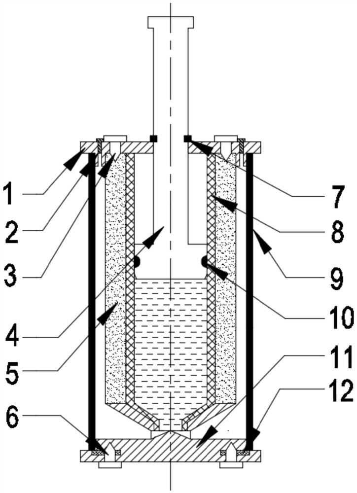
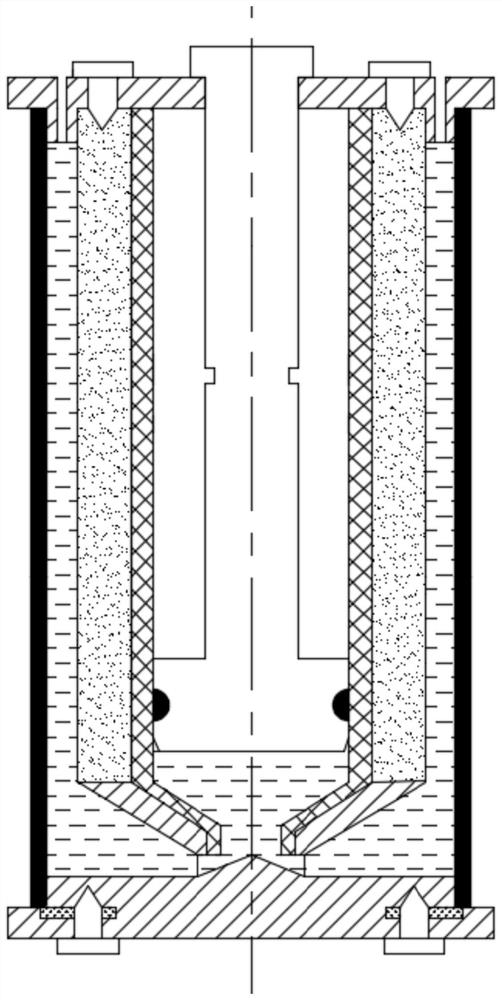
The invention provides a piston liquid injection type metal-air battery. The piston liquid injection type metal-air battery mainly comprises a metal anode, an air cathode, a top cover, a base, a positive pole, a negative pole and a piston device. The metal anode is a hollow tubular sleeve fixed between the top cover and the base; the inner side surfaces of the upper and lower ends of the air cathode are fixed on the side surfaces of the top cover and the bottom cover and keep a certain distance from the metal anode; the positive pole and the negative pole are fixed on the top cover and the base and are respectively connected and fixed with the current collector and the metal anode; and the piston device comprises a piston cylinder, a piston rod and a rubber ring and is integrally arranged in a center hole of the metal anode. The piston rod is fixed to the top cover through a clamping ring. When the electrolyte is injected, the hole plug on the top cover is pulled up, the clamping ring is removed, the piston rod is pushed, and the electrolyte is injected into a cavity between the air cathode and the metal anode under the action of pressure. The piston liquid injection mode provided by the invention is simple and convenient to operate, the space utilization rate of the battery is improved, and a reference is provided for industrialization of the metal-air battery.

Description

technical field [0001] The invention relates to the field of energy batteries, in particular to a piston liquid-injected metal-air battery and a method for using the same. Background technique [0002] A metal-air battery, the principle of which is to obtain oxygen from the air to carry out the redox reaction, a metal-air battery in which an oxygen reduction catalytic material is provided in the positive electrode, and the material is used to carry out the redox reaction on the oxygen in the adsorbed air . When discharging, the metal is oxidized into metal ions at the negative electrode, and the metal moves to the positive electrode side. On the other hand, at the positive electrode, oxygen in the air is reduced to produce hydroxide ions, which combine with the metal ions to form hydroxides. As a clean energy source with high energy density, metal-air batteries have broad application prospects. At present, many countries in the world, including my country, have carried ou...

Claims


Application Information

Patent Timeline
Patent Type & Authority Applications(China)
IPC IPC(8): H01M12/06H01M50/609H01M50/682
CPCH01M12/06H01M50/609H01M50/682Y02E60/10
Inventor 李岩龚昊丁晨
Owner 烟台浩忆生物科技有限公司
Why Eureka
Try Eureka