

Method for intensifying explosion-proof pipes by induction fusion welding and surfacing subareas on fire-facing side of boiler pipeline
A technology for explosion-proof pipes and pipes, which is applied in the field of induction fusion welding and surfacing welding to strengthen explosion-proof pipes. It can solve the problems of uniform sandblasting in the surfacing welding area of pipe rows and affect the quality of surfacing welding of pipe rows, so as to achieve high production efficiency and ensure melting Welding quality, uniform effect of sandblasting
- Summary
- Abstract
- Description
- Claims
- Application Information
AI Technical Summary
Problems solved by technology
Method used
Image

Examples
Embodiment Construction
[0036] The following will clearly and completely describe the technical solutions in the embodiments of the present invention with reference to the accompanying drawings in the embodiments of the present invention. Obviously, the described embodiments are only some, not all, embodiments of the present invention. Based on the embodiments of the present invention, all other embodiments obtained by persons of ordinary skill in the art without making creative efforts belong to the protection scope of the present invention.
[0037] Implementation column one
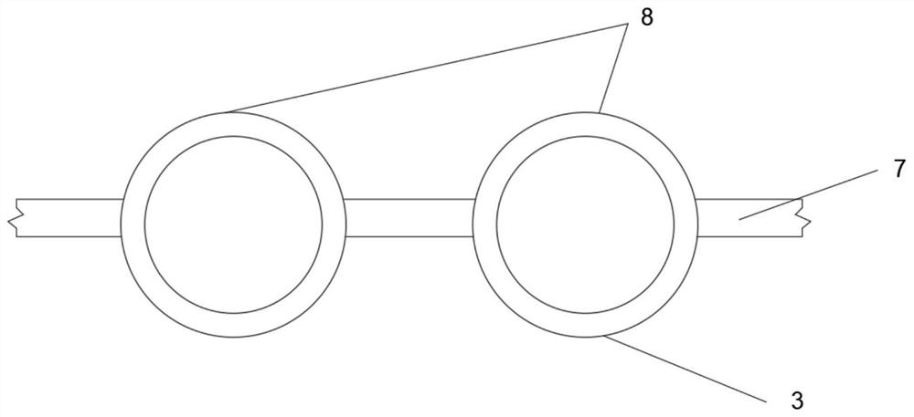
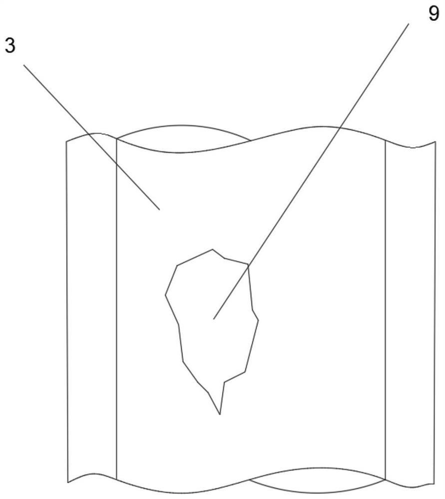
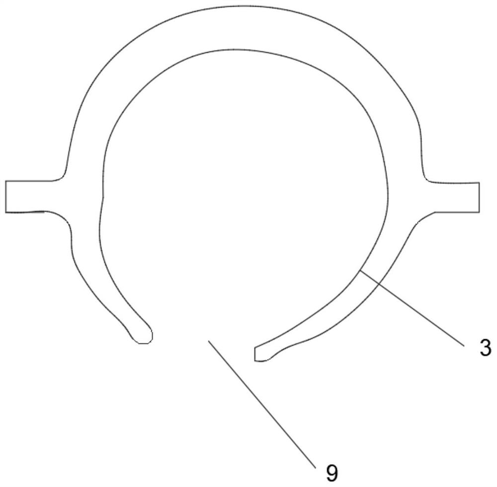
[0038] see Figure 1 to Figure 4 , a method for strengthening explosion-proof pipes by induction welding and surfacing welding of boiler pipes to the fire side, which is divided into the following steps:
[0039] (1) Prepare surfacing and spraying powder materials, purchase inconel625 superalloy welding wire surfacing materials; purchase nickel-based self-fluxing alloy powder induction welding materials.
[0040] (2) The au...
PUM
 Abstract
Description
Claims
Application Information