Flour tank capable of storing flour for long time
A technology for long-term storage and flour tanks, which is applied in the direction of anti-rot containers, bottle/can parts, separation methods, etc., and can solve the problems of flour being susceptible to moisture deterioration and dust accumulation
- Summary
- Abstract
- Description
- Claims
- Application Information
AI Technical Summary
Problems solved by technology
Method used
Image
Examples
Embodiment 1
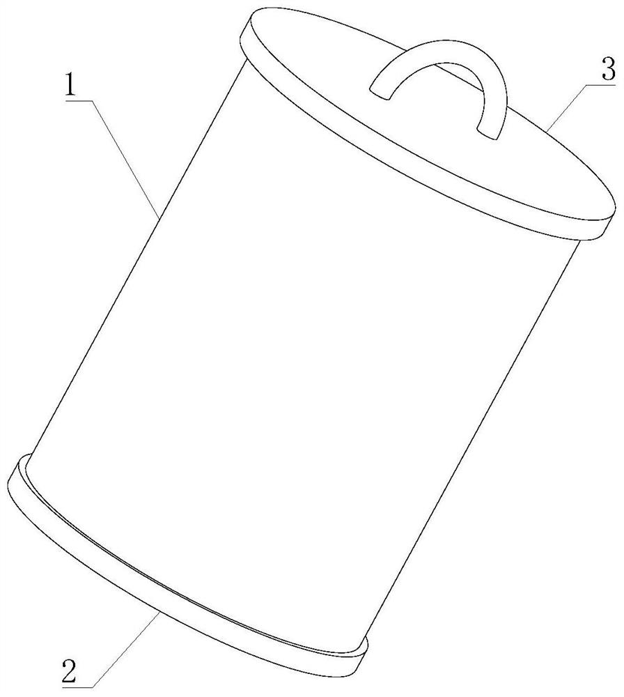
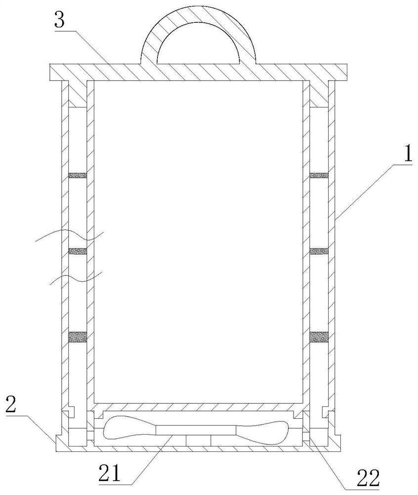
[0040] Such as Figure 1-6 As shown, the present invention provides a flour tank capable of long-term storage of flour, comprising a tank body 1 and a sealing cover 3, the sealing cover 3 is movably mounted on the upper end of the tank body 1, and the lower end of the tank body 1 is fixedly connected with a base 2.
[0041] In this embodiment, the tank body 1 is used for internal dust removal and flour storage, the base 2 is used for bottom support and dehumidification and drying inside the tank body 1 , and finally the tank body 1 is sealed by the sealing cover 3 .
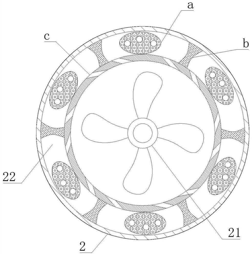
[0042] Such as Figure 1-6 As shown, in this embodiment, preferably, the base 2 includes an inner drying system 22, the inner drying system 22 is fixedly installed on the lower bottom surface of the tank body 1, and the inner middle position of the inner drying system 22 is fixedly installed with a circulating wind power supply system 21. The inner drying system 22 includes a drying ball a, the drying ball a is ...
Embodiment 2
[0044] Such as Figure 1-6 As shown, on the basis of Example 1, the present invention provides a technical solution: preferably, the drying ball a is a hollow ellipsoid, and the drying ball a is used for circulating the wind control flow inside the base 2 and dehumidifying inside the tank 1, A desiccant filter screen a1 is fixedly installed on the inner upper end of the drying ball a, a flow control pad a2 is fixedly installed on the inner lower surface of the drying ball a on the left side, and a moisture drying hole a3 is opened on the upper surface of the drying ball a.
[0045] In this embodiment, a desiccant filter screen a1 is arranged inside the desiccant ball a, and calcium chloride particles are placed on the upper end of the desiccant filter screen a1 as a desiccant. The desiccant ball a is placed inside the base 2, and the inside of the base 2 The upper end is directly connected to the interlayer of the double-layer tank wall 11. When humid air is generated inside t...
Embodiment 3
[0047] Such as Figure 1-6 As shown, on the basis of Example 1, the present invention provides a technical solution: preferably, diversion holes a4 are opened on the left and right sides of the drying ball a, and turbulence passages are opened in the left and right sides of the flow control pad a2 a5, there is a flow control channel a6 between the desiccant filter screen a1 and the flow control pad a2. a6 can slow down the flow rate and flow rate of the circulating airflow.
[0048] In this embodiment, the flow control pad a2 changes the shape of the inner bottom of the drying ball a, so that the flow control channel a6 appears at the inner bottom of the drying ball a. The width of the left side is designed, and the circulation hole c adopts an inclined design in the inner wall of the base 2. The inclined design makes the airflow generated by the fan of the circulation wind supply system 21 flow counterclockwise after entering the circulation hole c, so that the slow airflow ...
PUM
 Abstract
Description
Claims
Application Information
 - R&D
- Intellectual Property
- Life Sciences
- Materials
- Tech Scout
- Unparalleled Data Quality
- Higher Quality Content
- 60% Fewer Hallucinations
Browse by: Latest US Patents, China's latest patents, Technical Efficacy Thesaurus, Application Domain, Technology Topic, Popular Technical Reports.
© 2025 PatSnap. All rights reserved.Legal|Privacy policy|Modern Slavery Act Transparency Statement|Sitemap|About US| Contact US: help@patsnap.com


