
Multistage EMI filter for motor controller

A motor controller and filter technology, applied in the modification of electrical components, power electronics, cooling/ventilation/heating transformation, etc., can solve the problems of large fixed equipment investment, large one-time investment in molds, and production costs, etc. Achieve the effect of reducing process complexity and equipment investment, avoiding the use of potting materials, and improving manufacturability

Pending Publication Date: 2021-11-16
浙江伊控动力系统有限公司
View PDF0 Cites 1 Cited by
  • Summary
  • Abstract
  • Description
  • Claims
  • Application Information

AI Technical Summary

Problems solved by technology

[0006] First, segmented current-carrying copper bars require multiple sets of molds for production, and the one-time investment in the molds is large; and additional processes are required for connection, the process is complicated and the cost is high
[0007] Second, the filter capacitors at all levels are connected through the PCB, which may lead to a longer grounding path, which is not conducive to EMC effects; and many processes such as wave soldering and PCB manufacturing are introduced in the production process, which is not conducive to supply chain management and quality control.
[0008] Third, the current-carrying copper bar is connected to the filter capacitor through the transfer part, resulting in more contact interfaces on the electrical connection path, high contact resistance, and no EMC effect
[0009] Fourth, the overall use of potting glue to ensure the fixation and electrical insulation of parts requires a large investment in fixed equipment, and the process requires higher quality control costs
[0010] Fifth, auxiliary materials such as potting glue and adhesive glue need to be cured under specific conditions. The next stage of operation can only be carried out after a certain curing time in the production process, and a specific carrier or curing storage site is required, which brings additional production costs

Method used


Image

  • Multistage EMI filter for motor controller
  • Multistage EMI filter for motor controller
  • Multistage EMI filter for motor controller

Examples


Embodiment Construction

[0031] The following description serves to disclose the invention to enable those skilled in the art to practice the invention. The preferred embodiments described below are given by way of example only, and other obvious modifications will occur to those skilled in the art. The basic principles of the invention defined in the following description may be applied to other embodiments, variations, improvements, equivalents, and other technical solutions without departing from the spirit and scope of the invention.

[0032] The invention discloses a multi-stage EMI filter for a motor controller. The specific embodiments of the invention will be further described below with reference to the preferred embodiments.

[0033] In the embodiments of the present invention, those skilled in the art should note that the negative electrode copper bar, the positive electrode copper bar, and the grounding copper bar involved in the present invention may be regarded as the prior art.

[0034...


PUM


Abstract

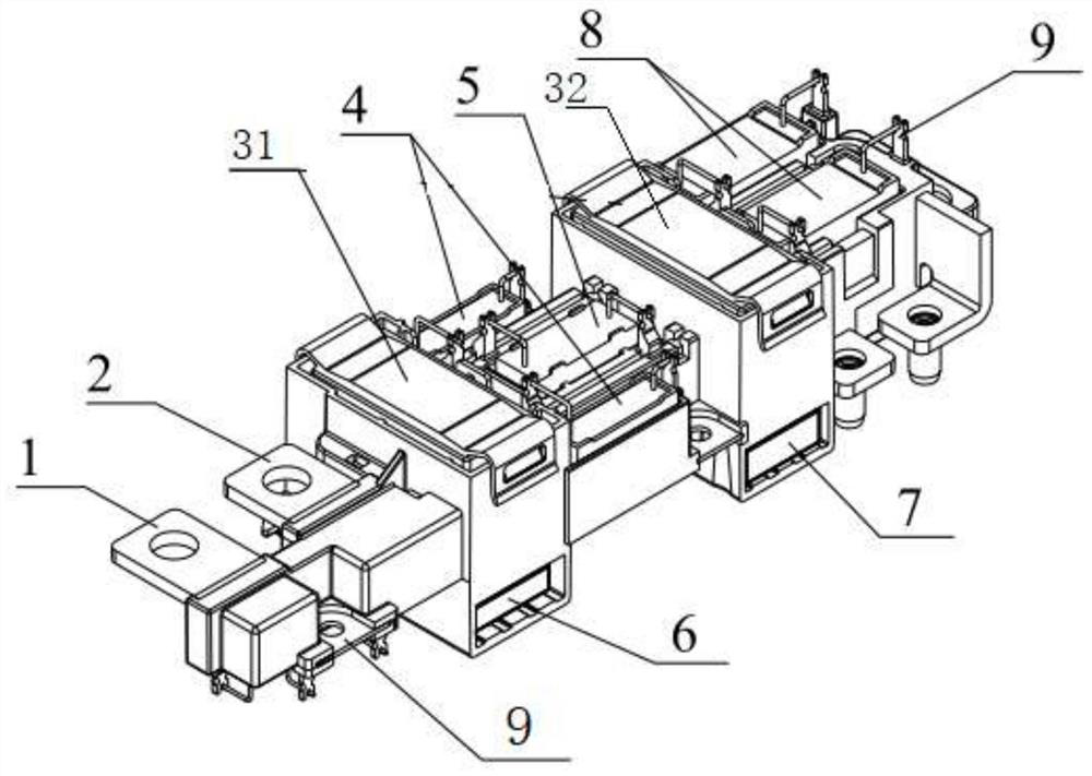
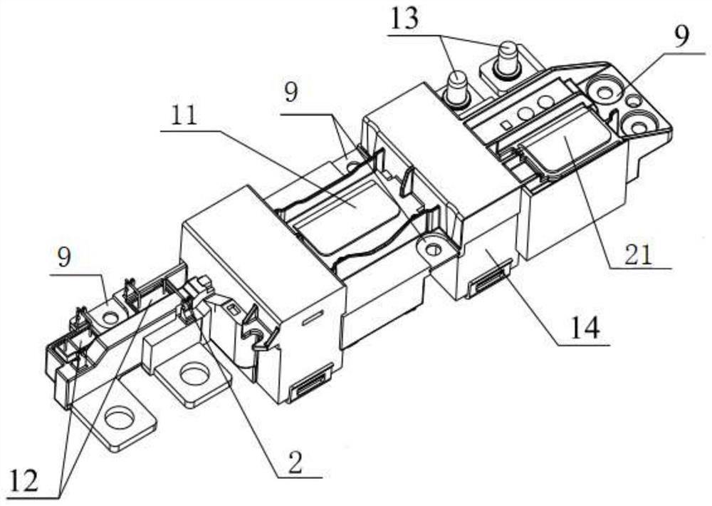
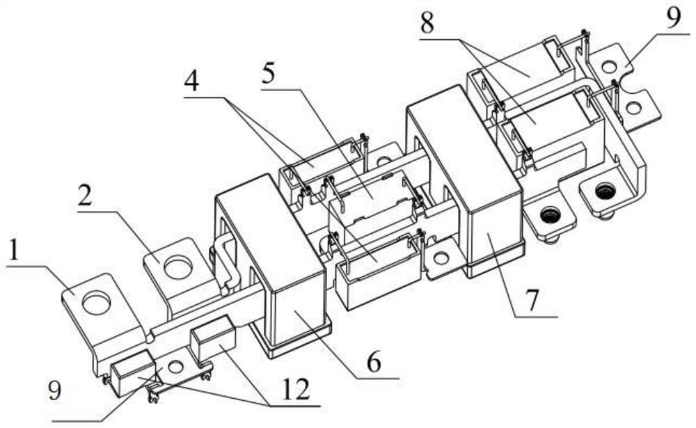
The invention discloses a multistage EMI filter for a motor controller, and the filter comprises an injection molding body, a negative electrode copper bar, a positive electrode copper bar, a magnetic core, a filter capacitor and a plurality of grounding copper bars; the negative electrode copper bar, the positive electrode copper bar and the plurality of grounding copper bars are mounted on the injection molding body; the negative electrode copper bar is provided with a first heat dissipation surface, and the positive electrode copper bar is provided with a second heat dissipation surface. The multi-stage EMI filter for the motor controller disclosed by the invention has the main functions of connecting the motor controller power module and the external direct current interface through the current-carrying copper bar, carrying out EMI filtering and providing a copper bar heat dissipation surface at the same time.

Description

technical field [0001] The invention belongs to the technical field of filters for motor controllers, and in particular relates to a multi-stage EMI filter for motor controllers. Background technique [0002] In the electric drive powertrain of new energy vehicles, the motor controller controls and drives the motor to run through power modules such as IGBTs. The higher operating frequency of the power module determines that electromagnetic filtering needs to be performed within a certain frequency range through a filtering device, so as to ensure The electric drive system has good EMC (Electro Magnetic Compatibility) performance, that is, electromagnetic compatibility performance. With the development of electric vehicles, the requirements for electromagnetic compatibility performance are getting higher and higher. [0003] Existing filter devices are mainly composed of current-carrying copper bars, magnetic rings, capacitors, printed circuit boards (PCBs), and injection-mo...

Claims


Application Information

Patent Timeline
Patent Type & Authority Applications(China)
IPC IPC(8): H02M1/44H05K7/20H02M1/12
CPCH02M1/44H05K7/20909H02M1/126
Inventor 王天奇赵平华
Owner 浙江伊控动力系统有限公司
Learn More