
Submarine multi-energy combined supply system with chemical upgrading heat storage function

A chemical and thermal storage technology, applied in thermal storage equipment, energy storage, indirect heat exchangers, etc., can solve the problems of reduced submarine cruising range, limited submarine mobility, and high cost of nuclear submarines, so as to reduce the consumption of liquid oxygen. , Guarantee the amount of fuel and safety, the effect of saving fuel

Active Publication Date: 2021-11-19
NORTH CHINA ELECTRIC POWER UNIV (BAODING)
View PDF6 Cites 0 Cited by
  • Summary
  • Abstract
  • Description
  • Claims
  • Application Information

AI Technical Summary

Problems solved by technology

The production of hydrogen is generally through fuel reforming to produce hydrogen, which requires a certain temperature to maintain the reaction. Generally, the combustion of methanol or phosphoric acid is used to provide heat for the reaction on the submarine, which requires the consumption of a part of the liquid oxygen and fuel storage of the submarine. , this will lead to a decrease in the cruising range of the submarine, and the action of the submarine will also be limited. This problem is inevitable for conventional submarines at this stage, and there is almost no energy power system used to solve fuel and liquid oxygen on conventional submarines in active service. The storage problem, nuclear submarines solve the fuel problem very well, but the cost of nuclear submarines is too expensive, so how to save fuel and liquid oxygen to the maximum extent for conventional submarines has become a difficult problem that must be solved; in addition, the power source of conventional submarines is diesel engines, relying on The diesel engine provides power for the submarine. During the working process, the diesel engine generates a large amount of waste heat. Most of the waste heat is not used, but is directly discharged into the sea after being cooled by sea water, resulting in a large waste of energy.

Method used


Image

  • Submarine multi-energy combined supply system with chemical upgrading heat storage function
  • Submarine multi-energy combined supply system with chemical upgrading heat storage function

Examples


Embodiment Construction

[0033] The principle and specific implementation of the present invention will be further described below in conjunction with the accompanying drawings.

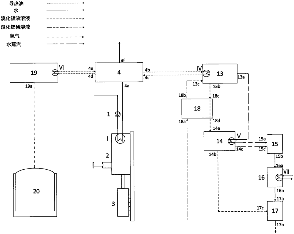
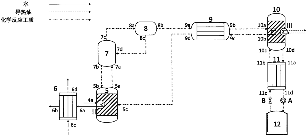
[0034] figure 1 It is a schematic diagram of the principle structure of a submarine multi-energy cogeneration system with chemical upgrading and thermal storage provided by the present invention. The composition, realization and connection of the system in the present invention are as follows: the system includes four subsystems, which are respectively a diesel power subsystem, a chemical upgrading heat storage subsystem, a hydrogen production and hydrogen storage subsystem, and a refrigeration subsystem. The diesel power subsystem is connected to the chemical quality upgrading heat storage subsystem through pipelines; the hydrogen production hydrogen storage subsystem is connected to the chemical quality upgrading heat storage subsystem through pipelines; the refrigeration subsystem is connected to the chemical quality upgr...


PUM


Abstract

The invention discloses a submarine multi-energy combined supply system with a chemical upgrading heat storage function, and belongs to the technical field of energy power. The system comprises four subsystems, namely a diesel power subsystem, a chemical upgrading heat storage subsystem, a hydrogen production and storage subsystem and a refrigeration subsystem. The system not only provides conventional power, but also can complete quality upgrading and heat storage of waste heat and provide hydrogen energy, heat energy and cold energy; fuel of a submarine is remarkably saved, and liquid oxygen consumption is reduced, so that the cruising mileage and concealment of the submarine are improved; the comprehensive energy utilization efficiency is improved; and the combat performance of the submarine is greatly improved.

Description

technical field [0001] The invention relates to a submarine multi-energy joint supply system with chemical quality improvement and thermal storage, belonging to the technical field of energy and power. Background technique [0002] In modern warfare, submarines have become an indispensable part of the modern navy due to their high concealment. Especially the development of nuclear powered submarines has brought a deadly threat to conventional powered submarines. And reducing the exposure rate and improving the concealment of submarines have always been the important development goals pursued by submarines. Except that nuclear-powered submarines can cruise underwater for a long time without being limited to fuel and oxygen, conventionally-powered submarines need to surface within a certain period of time to supplement the oxygen needed for diesel engine combustion, which increases the chance of submarine exposure. Therefore how to improve the underwater cruising time and co...

Claims


Application Information

Patent Timeline
Patent Type & Authority Applications(China)
IPC IPC(8): F25B15/06F28D20/00F01K27/00F01D15/10
CPCF25B15/06F28D20/003F01K27/00F01D15/10F25B2400/24Y02E60/14Y02E70/30Y02A30/27
Inventor 冉鹏周霄
Owner NORTH CHINA ELECTRIC POWER UNIV (BAODING)
Learn More