
Pressure transmitter and assembling method thereof

A transmitter and pressure sensor technology, applied in the field of pressure transmitter and its assembly, can solve the problems of low quality, complex process, complex structure, etc., achieve stable and more durable electrical connection, avoid manual welding wires, and realize shielding signal effect

Pending Publication Date: 2021-11-19
MICRO SENSOR
View PDF7 Cites 0 Cited by
  • Summary
  • Abstract
  • Description
  • Claims
  • Application Information

AI Technical Summary

Problems solved by technology

[0003] Pressure transmitters on the market are usually composed of pressure sensors, circuit boards, bases, housings, electrical connectors, and external connectors. The electrical components are loaded into the base and housing, and solidified by potting, welding, and threading. Fix it by other means, and complete the electrical connection by welding wires or welding electrical connectors. This kind of pressure transmitter has many parts and complex structure, and requires manual labor to complete a series of processes such as production, calibration, testing, and assembly. complex and low quality
At the same time, due to the application characteristics of pressure transmitters, the diversity of customer requirements is high, the degree of customization is high, and the diversity of structures is also large, because it is difficult to realize automatic production
However, as society develops towards intelligence and automation, the demand for pressure transmitters will increase. The current production mode of manual assembly cannot meet the requirements. Automatic production of pressure transmitters is already imminent, but the current common This structure is unsatisfactory and not suitable for mechanical automatic production such as mechanical identification, mechanical picking and assembly

Method used


Image

  • Pressure transmitter and assembling method thereof
  • Pressure transmitter and assembling method thereof
  • Pressure transmitter and assembling method thereof

Examples


Embodiment Construction

[0034] The present invention is described in further detail below in conjunction with accompanying drawing:

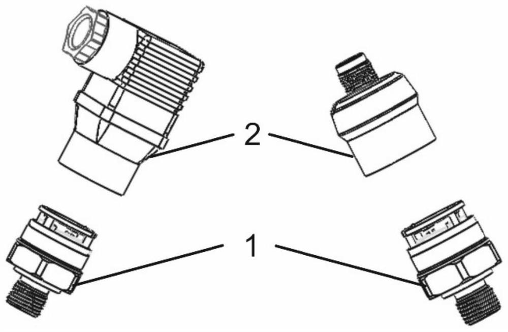
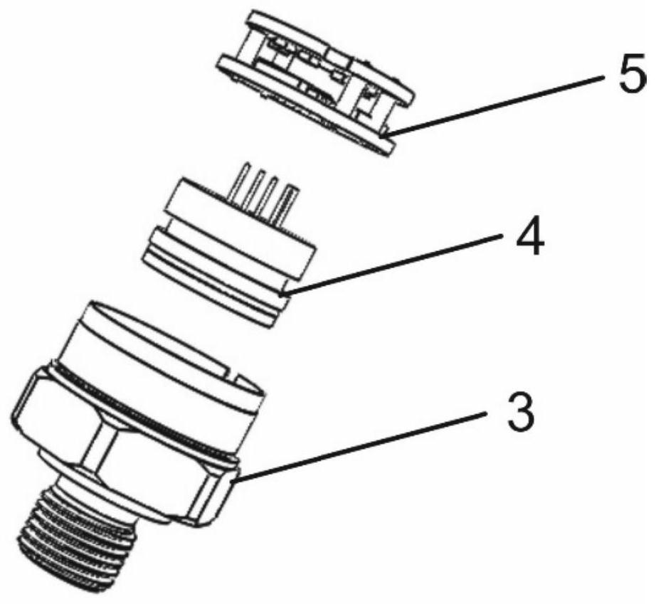
[0035] Such as figure 1 As shown, the present invention provides a pressure transmitter fully applicable to automatic production, which mainly includes two parts, Core module 1 and connector plug 2 . Modular design, the components that need to be configured according to the needs of customers are integrated into Core A components, and the rest of the standardized components are integrated into one, which solves the structural diversity caused by the diverse needs of customers and makes it impossible to carry out automated production. The design of all mechanisms has a positioning Card position structure, no wire connection, fully welded structure, can realize the structure manufacturing of automatic production and is suitable for use on the automatic production line of calibration.

[0036] Core module 1 includes a base 3, a pressure sensor 4 and a PCB assembly 5 coax...


PUM


Abstract

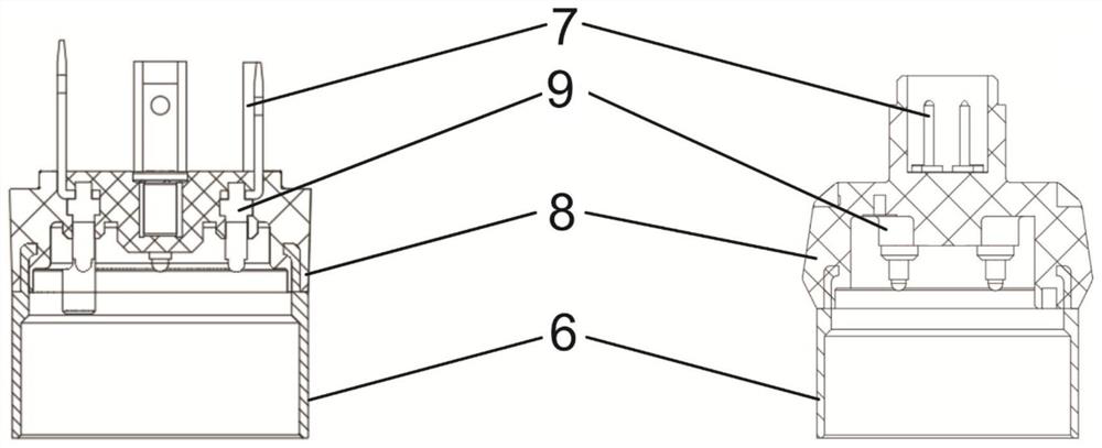
The invention discloses a pressure transmitter and an assembling method thereof. The pressure transmitter comprises a Core module and a connector plug; the Core module comprises a foundation, a pressure sensor and a PCB assembly which are coaxially connected in sequence, the foundation comprises a base and a metal cylinder, the pressure sensor is located at the top of the base and located in the metal cylinder, and a sensor positioning groove is formed in the top of the base; the end, facing the PCB assembly, of the metal cylinder is provided with a clamping groove, and the end, facing the metal cylinder, of the PCB assembly is provided with radial protruding points. the connector plug comprises a shell, an electrical connection socket, a pogo pin and an electrical connection pin which are coaxially connected in sequence, and the electrical connection socket is formed by integrated injection molding; and the end, away from the foundation, of the PCB assembly is located in the shell and connected to the pogo pin, and the end, away from the foundation, of the PCB assembly is provided with a plug positioning groove. Structural manufacturing of automatic production can be achieved, and the method can be used for a calibrated automatic production line.

Description

technical field [0001] The invention belongs to the field of pressure transmitters, and relates to a pressure transmitter and an assembly method thereof. Background technique [0002] A pressure transmitter is a sensor-based device that converts pressure signals into electrical signals. Because it can convert pressure into visual data, it is widely used in various fields such as industry, construction, military, and medical treatment. field. [0003] Pressure transmitters on the market are usually composed of pressure sensors, circuit boards, bases, housings, electrical connectors, and external connectors. The electrical components are loaded into the base and housing, and solidified by potting, welding, and threading. Fix it by other means, and complete the electrical connection by welding wires or welding electrical connectors. This kind of pressure transmitter has many parts and complex structure, and requires manual labor to complete a series of processes such as produc...

Claims


Application Information

Patent Timeline
IPC IPC(8): G01L1/00G01L19/00B23P21/00
CPCG01L1/00G01L19/00G01L19/0061B23P21/00
Inventor 王刚徐东魏娜潘骏驰
Owner MICRO SENSOR
Learn More