Off-axis two-reflector multi-light-in-one optical main system

A main system, off-axis technology, applied in optics, optical components, instruments, etc., can solve the problems of reducing the effective clear aperture and imaging performance, the system is large, and the volume is large, so as to eliminate the reduction of the effective aperture and reduce the structure Large volume, the effect of suppressing mutual interference

Pending Publication Date: 2021-11-19
CHANNGCHUN CHANGGUANG ADVANCED OPTICS TECH CO LTD
View PDF0 Cites 2 Cited by
  • Summary
  • Abstract
  • Description
  • Claims
  • Application Information

AI Technical Summary

Problems solved by technology

However, most of the main systems adopt the RC coaxial catadioptric optical structure. Although it can ensure that each waveband of the system passes through the main system at the same time and then images separately, which reduces the problem of large system volume, the secondary mirror in the system is obstructed. The effective light aperture and imaging performance of the system are reduced; the structure of the off-axis three-mirror optical system without central occlusion is the best in optical performance, but its inherent defects are large volume and off-axis arrangement in the Y direction The main mirror and three mirrors lead to the system volume is too large, it is difficult to adapt to the application of the airborne pod environment

Method used


Image

  • Off-axis two-reflector multi-light-in-one optical main system
  • Off-axis two-reflector multi-light-in-one optical main system
  • Off-axis two-reflector multi-light-in-one optical main system

Examples


Embodiment 1

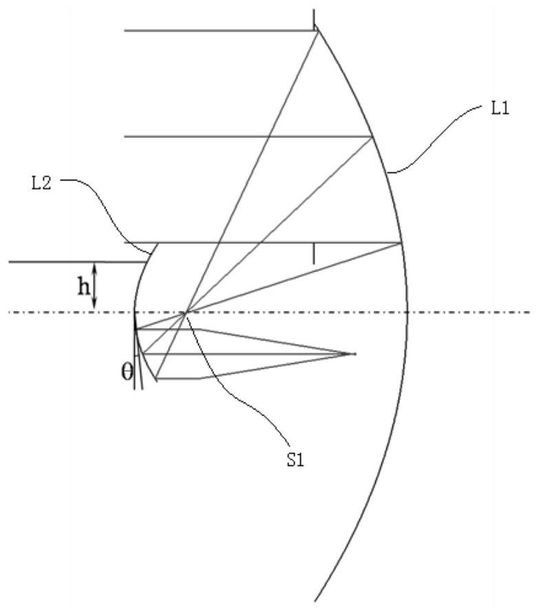
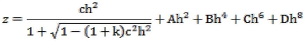
[0028] Such as figure 1 As shown, the off-axis two-mirror multi-light combined optical main system of the present invention includes an off-axis primary mirror L1 and an off-axis secondary mirror L2; the off-axis primary mirror L1 and the off-axis secondary mirror L2 are both positive power reflectors , the reflective surface is a rotationally symmetrical even-order aspheric surface, and its surface equation is as follows:

[0029]

[0030] Where z is the axis of rotational symmetry of the aspheric surface, c is the radius of curvature of the rotationally symmetric even-order aspheric surface, h is the radial coordinate, and k is the conic conic coefficient.

[0031] The function of the off-axis primary mirror L1 is to image an object at infinity on the primary image plane, and the function of the off-axis secondary mirror L2 is to shrink the image formed by the off-axis primary mirror L1 and emit parallel rays of a certain magnification.

[0032] The off-axis primary mirr...

Embodiment 4

[0049] Such as figure 1 As shown, the difference between this embodiment and Embodiment 1 is that the reflection surface of the off-axis primary mirror L1 adopts a high-order aspheric surface, and the surface parameter of the high-order aspheric surface is k: -1.05~-0.57; A : 0; B: 1E-17 ~ 9E-17; C: 1E-22 ~ 9E-22; D: 1E-26 ~ 9E-26, the purpose is to further increase the imaging of the off-axis two-mirror multi-light combined optical main system Field of view, the high-order aspheric surface has a strong correction ability for off-axis asymmetric coma and astigmatism, and the off-axis aberration increases significantly with the increase of the system field of view. field increase.

[0050] The difference between Embodiments 5 and 6 and Embodiment 4 lies in that the parameters of the reflecting surface are different, and the others are the same.

[0051] Refer to Table 4 for the off-axis primary mirror L1 and off-axis secondary mirror L2 reflection surface parameters of Embodi...

Embodiment 7

[0059] Such as figure 1 As shown, the difference between this embodiment and Embodiment 1 is that the off-axis secondary mirror L2 adds the amount of tilt (that is, the alpha rotation angle in the X direction) and the eccentricity in the Y direction instead of only off-axis, and its purpose is to correct the off-axis in the system. Both the on-axis primary mirror L1 and the off-axis secondary mirror L2 are off-axis asymmetric field curvature brought about by positive refractive power. The field curvature correction of the rear component optical system is easier, and the optical axis of the outgoing light can be aligned with the optical axis of the incident light. The processing is parallel, which is more suitable for the layout of the rear group of optical components; the alpha rotation angle in the X direction is -0.1°~-0.5°, and the eccentricity in the Y direction is 0.1~0.5mm.

[0060] The difference between Embodiments 8 and 9 and Embodiment 7 lies in the parameters of the...


PUM

PropertyMeasurementUnit
radiusaaaaaaaaaa

Abstract

The invention relates to an off-axis two-reflector multi-light-in-one optical main system. The system comprises an off-axis primary mirror and an off-axis secondary mirror. The off-axis primary mirror and the off-axis secondary mirror are both positive-focal-power reflectors, and the reflecting surfaces are both rotational symmetric even-order aspheric surfaces. The off-axis primary mirror converges incident parallel light rays at a focal point of the off-axis primary mirror, and a primary image surface field diaphragm is arranged at the focal point; the focus of the off-axis secondary mirror coincides with the focus of the off-axis primary mirror, and the light passing through the focus is reflected by the off-axis secondary mirror and then emits parallel light. The technical problems that an existing airborne optical load main system has central obscuration and the system volume is large are solved at the same time, full-spectrum-band imaging detection can be achieved theoretically, mutual interference caused by respective imaging of all spectrum bands is effectively restrained, all systems can achieve the optimal image quality, and the method is suitable for being applied to a large-aperture long-focal-length system in an airborne environment.

Description

technical field [0001] The invention belongs to the technical field of optical design, and relates to an off-axis two-mirror multi-light combined optical main system. Background technique [0002] At present, the multi-detection range and resolution of my country's airborne pods are only sufficient for low-altitude or medium-low altitude use. To meet high-altitude and ultra-long-distance all-day detection, the optical load must increase the focal length and aperture, and at the same time increase the detection band. Distance detection and identification; laser is used for distance determination, adding detection information of the distance dimension to the system. The volume and weight of optical loads are particularly important in aviation pods. Multiple optical loads with long focal lengths and large apertures are arranged separately, which makes it difficult to achieve an effective and reasonable arrangement of space, resulting in mutual constraints among various systems...

Claims


Application Information

Patent Timeline
Patent Type & Authority Applications(China)
IPC IPC(8): G02B17/06G02B27/30G02B27/09
CPCG02B17/0615G02B27/30G02B27/0983
Inventor 曲贺盟管海军王超
Owner CHANNGCHUN CHANGGUANG ADVANCED OPTICS TECH CO LTD
Why Eureka
Try Eureka