Fiber laser health monitoring method

A fiber laser and health monitoring technology, which is applied in the direction of laser monitoring devices, lasers, optical instrument testing, etc., can solve problems such as abnormal rise, failure of fiber laser power supply, optical path failure monitoring, failure of temperature and humidity monitoring, etc., to achieve convenient The effect of mastering

Inactive Publication Date: 2021-11-19
INST OF ELECTRONICS ENG CHINA ACAD OF ENG PHYSICS
View PDF12 Cites 1 Cited by
  • Summary
  • Abstract
  • Description
  • Claims
  • Application Information

AI Technical Summary

Problems solved by technology

The disadvantage of this method is that it can only judge the state of the optical sensor module through the read level, and then judge whether the optical path is abnormal, and cannot judge the specific cause of the abnormal optical path, and can only monitor the failure of no light, and cannot monitor Abnormal conditions of optical power decrease and increase, unable to monitor abnormal conditions of physical quantities such as temperature and humidity
The disadvantage of this method is that it can only monitor the breakage of the optical fiber, but cannot monitor whether the fiber laser circuit, temperature, and humidity are normal.
The disadvantage of this method is that it is necessary to emit light through a visible light laser to measure whether there is visible light in each section of optical fiber, and judge whether each section of optical fiber is abnormal according to the monitoring results
The disadvantage of this method is that it can only monitor the faults of the optical fiber communication network, but cannot monitor the faults of the fiber laser power supply and optical path, and cannot monitor whether the physical quantities such as temperature and humidity are normal.

Method used


Image

  • Fiber laser health monitoring method
  • Fiber laser health monitoring method
  • Fiber laser health monitoring method

Examples


Embodiment 1

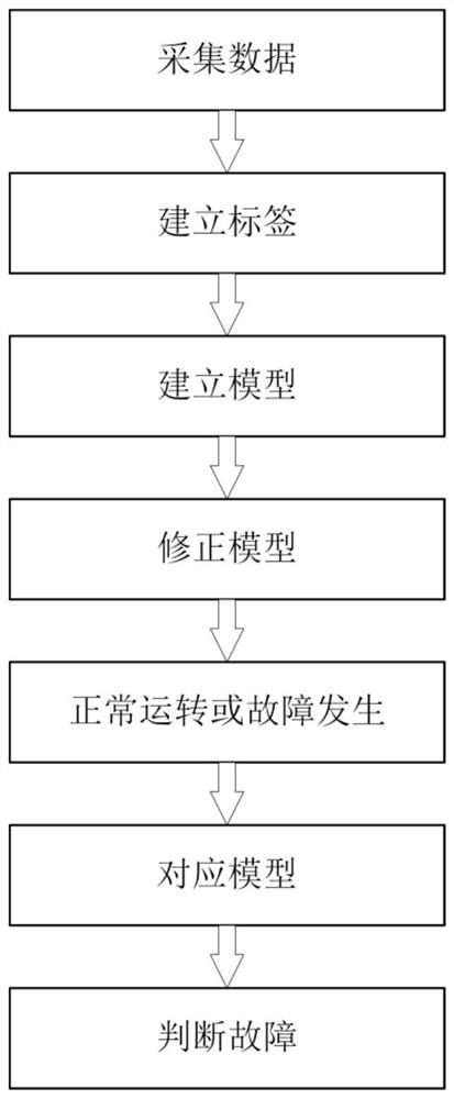
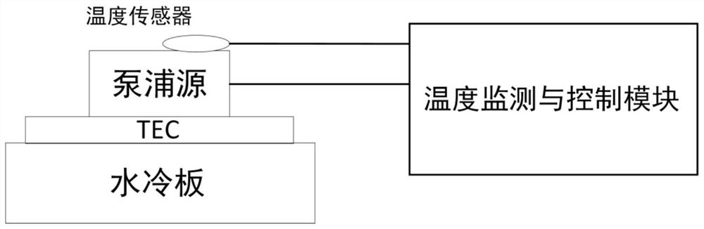
[0064] Firstly, the measured data set of the pump source temperature is collected for the fiber laser. The pump source temperature acquisition consists of several modules: the pump temperature parameter acquisition module is used to collect the current pump source temperature through one or more sensors to generate one or more collected temperatures. The microprocessor module is connected with the temperature parameter acquisition module, and is used for analyzing one or more collected temperatures and generating corresponding control instructions. The control output module is connected with the microprocessor module and is used for generating a driving signal according to the control instruction of the microprocessor module. The power supply module is used for supplying power to the temperature parameter acquisition module, the control output module and the microprocessor module.

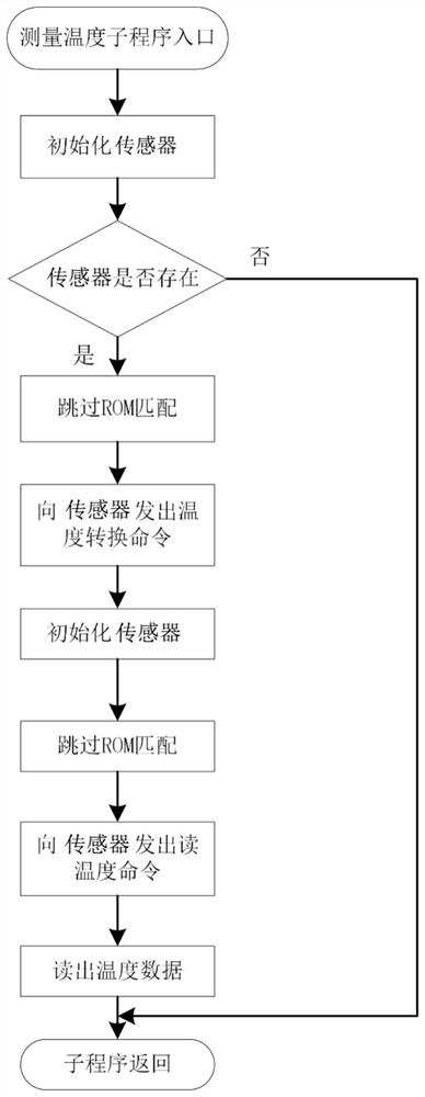
[0065] For the temperature acquisition process, refer to the attached figure 2 , measuring t...

Embodiment 2

[0072] The fiber laser pump source works by direct injection of carriers, and the stability of the injection current has a direct impact on the output of the laser. Factors such as surge impact, electrostatic breakdown, and forward overcurrent can easily damage the laser. The driving current of the pump source is a constant current with small ripple and few glitches, and the working safety of the pump source needs to be considered at the same time.

[0073] Acquisition of driving current: The current acquisition circuit uses the method of converting series resistance into voltage for measurement, collects the voltage in the circuit through a 50mΩ resistance, and converts the collected tiny voltage signal into a voltage signal range that the microprocessor can handle through the op amp . An operational amplifier is used that accurately amplifies differential input voltages with positive high common-mode voltages greater than 500V. The collected voltage divided by the resistan...

Embodiment 3

[0079]The oscillator of the fiber laser controls the excitation of the fiber according to the input laser output command value or current command value to obtain the desired laser output. The output power of the oscillator is the most important parameter of the oscillator, which seriously affects the working state of the laser.

[0080] Oscillator output power acquisition: According to the structure of the fiber laser system, the sampling optical path of the laser output power real-time monitoring device involved is mainly composed of the main optical path sampling mirror and optical attenuator. The sampling optical path is shown in the attached Figure 4 shown.

[0081] In order to achieve real-time monitoring of laser power without affecting the output laser used in the work, a high-transmittance beam splitter with an angle of 45° to the output light is added to the main optical path of the output light, and the tiny reflection of the sampling mirror is used The light sampl...


PUM


Abstract

The invention relates to a fiber laser health monitoring method. The method comprises an optical fiber laser data acquisition method and optical fiber laser operation model establishment, and judges the fault reason of an optical fiber laser by comparing the acquired data and the operation model with the actual working state of the optical fiber laser. Measurement data with high linear correlation are collected, analyzed and processed, main changes of measurement variables can be reflected, and noise and interference in the monitoring process can be reflected through a large amount of data. Data are sampled according to time, the correlation between different parameters can be reflected, and the reason of the fault can be jointly judged. The statistical regularity of the process is estimated through potential information in the time sequence, and the method is simple, easy to implement and convenient to master. According to the invention, whether physical quantities such as temperature, humidity, current, voltage and the like of the fiber laser fail or not can be comprehensively monitored, full-automatic laser monitoring can be realized, and reasons for failure of the fiber laser can be judged.

Description

technical field [0001] The invention belongs to the technical field of real-time health monitoring systems for lasers, and in particular relates to real-time health monitoring systems and methods with structures such as fiber lasers, water coolers, and control modules. Background technique [0002] The optical fiber amplifier developed by using optical fiber doped with rare earth elements has brought revolutionary changes to the field of light wave technology. Because the fiber core in the fiber laser is very thin, it is easy to form a high power density in the fiber under the action of the pump light, resulting in the inversion of the number of laser energy level particles of the laser working material. Therefore, the laser oscillation can be formed by properly adding a positive feedback loop to form a resonant cavity. Fiber laser is an efficient wavelength converter, which converts the pump laser wavelength to the lasing wavelength of doped rare earth ions. Just because ...

Claims


Application Information

Patent Timeline
IPC IPC(8): H01S3/00G01M11/00
CPCH01S3/0014G01M11/00
Inventor 李思敏刘友江秋勇涛
Owner INST OF ELECTRONICS ENG CHINA ACAD OF ENG PHYSICS
Why Eureka
Try Eureka