Separation type phase change heat dissipation inversion device

An inverter device, a separate technology, applied in the field of separate phase-change heat dissipation inverter devices, can solve the problems of thermal breakdown of internal power devices, troublesome installation and operation, and frozen cracked pipes, etc., achieving simple structure and low cost. The effect of low and prolonging the service life

Pending Publication Date: 2021-11-19
XINFENGGUANG ELECTRONICS TECH CO LTD
View PDF12 Cites 0 Cited by
  • Summary
  • Abstract
  • Description
  • Claims
  • Application Information

AI Technical Summary

Problems solved by technology

However, water cooling also has its drawbacks. Many power inverter devices are high-voltage equipment, which require multiple units to be used in series. The cooling water needs to use deionized cooling water, because there are many pipe connections, there is a hidden danger of water leakage, because the air and objects The fine dust on the surface and the leaked deionized water quickly become conductive water, which may cause a short circuit and cause serious accidents. Natural water, pure water or deionized water are all corrosive to a certain extent. The risk is high; the freezing point temperature of the cooled deionized water is relatively high, with 50% ethylene glycol additive added, the freezing point is less than -35°C, and there is a possibility of freezing and cracking the pipeline in winter
At the same time, the deionization adsorption device in the high-pressure equipment has become an accessory device that must be added, and it is generally required to be replaced once a year. In this way, the cost will increase, and the installation and operation and maintenance will be more troublesome.
[0007] In addition, no matter it is air-cooled or water-cooled, for the same inverter device, as the power of the inverter device increases, the calorific value increases year-on-year, and the temperature rise also increases year-on-year. If the protection is not protected, it will cause thermal breakdown of the internal power device, resulting in serious failure

Method used


Image

  • Separation type phase change heat dissipation inversion device
  • Separation type phase change heat dissipation inversion device
  • Separation type phase change heat dissipation inversion device

Examples


Embodiment Construction

[0026] The present invention will be further described below in conjunction with the accompanying drawings and embodiments.

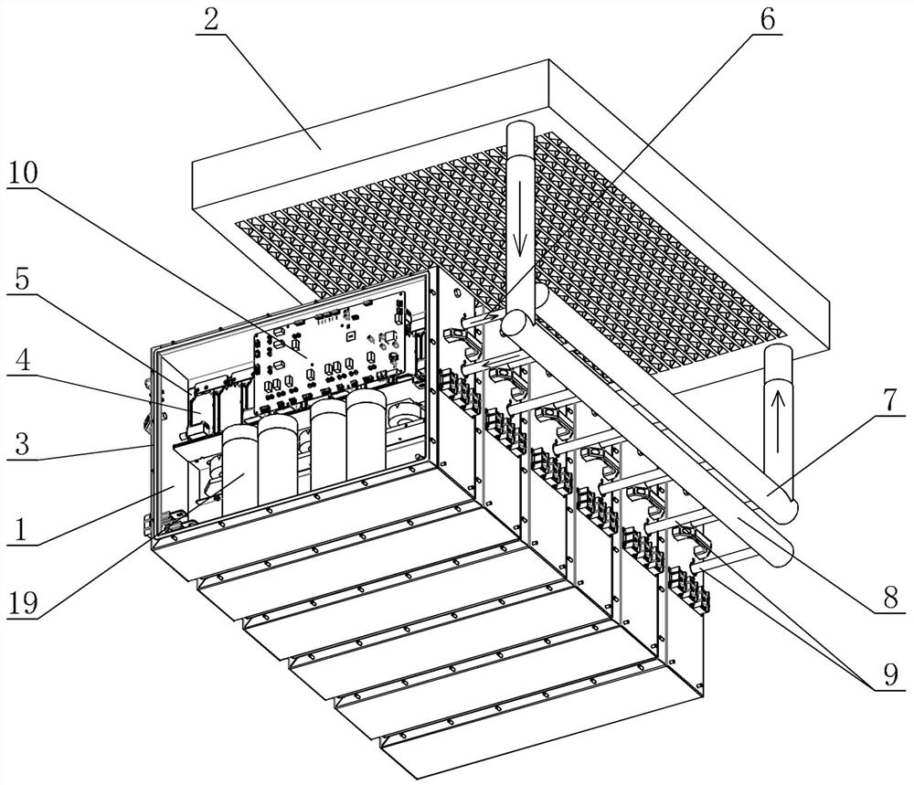
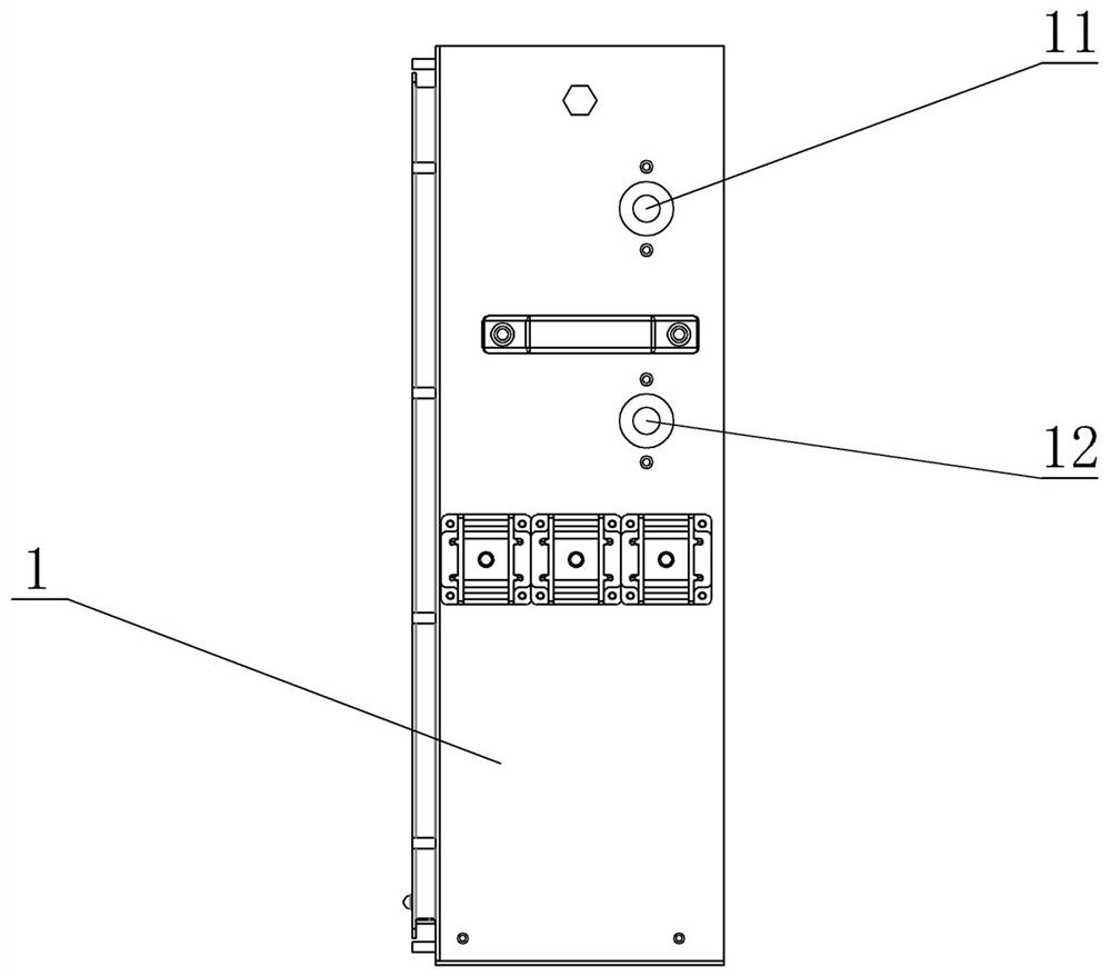
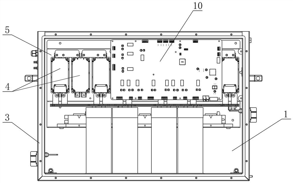
[0027] Such as figure 1 As shown, the perspective view of the inverter device of the separated phase change heat dissipation of the present invention is given, figure 2 and image 3 The front view and the left view of the power unit in the present invention are given respectively, which are composed of multiple power units 1, a heat exchanger 2, a cooling plate 5, an outflow main pipe 7, an outflow branch pipe 6, a return main pipe 8, and a return branch pipe 9 The power unit 1 is composed of a unit case 3 and a control circuit board 10 arranged in the unit case 3, an electrolytic capacitor 19 and a plurality of semiconductor power devices 4, and the semiconductor power devices 4 are reversed under the control of the control circuit board 10. change jobs. Each power unit 1 shown is provided with a cooling plate 5, and the semiconductor power device ...


PUM


Abstract

The invention relates to a separation type phase change heat dissipation inversion device which comprises power units and a heat exchanger, wherein each power unit is composed of a shell and a semiconductor power device; a cooling plate is arranged in each power unit, each semiconductor power device is fixed on the corresponding cooling plate, the heat exchanger is located outside the unit shells, a medium outlet of each cooling plate is communicated with an outflow header pipe through an outflow branch pipe, and the outflow header pipe is communicated with an inlet of the heat exchanger; an outlet of the heat exchanger is communicated with a medium inlet of each cooling plate through a backflow main pipe and a backflow branch pipe; and the cooling plates and the heat exchanger are filled with a cooling medium. According to the separation type phase change heat dissipation inversion device, heat generated by the semiconductor power devices can be taken away by utilizing the property that the medium can absorb a large amount of heat while the temperature is not increased during vaporization, so that the junction temperature of the semiconductor power devices is maintained in a proper temperature state, the taken-away heat is dissipated to the external environment through the heat exchanger, and the long-term stable and reliable operation of the inversion device is ensured.

Description

technical field [0001] The present invention relates to a separate phase-change heat dissipation inverter device, and more specifically, to a cooling medium that can absorb a large amount of heat during phase change (vaporization) without increasing the temperature to ensure long-term cooling of semiconductor power devices. Stable and reliable separated phase change heat dissipation inverter device. Background technique [0002] At present, inverter devices made of semiconductor power devices are widely used in power electronic equipment. In this type of device, DC power is usually converted into AC power, or AC power is converted into DC power and then converted into AC power of different frequencies. During this change process, the frequency usually changes, and the high-voltage dynamic reactive power compensation device (SVG), high-voltage frequency converter, high-voltage energy storage PCS device, and energy feedback device all use the high-speed switching function of p...

Claims


Application Information

Patent Timeline
Patent Type & Authority Applications(China)
IPC IPC(8): H05K7/20H02M1/00
CPCH05K7/20409H05K7/20509H05K7/20354H02M1/00
Inventor 梁开来宋林林刘继新蔡宝柱马彦兵伊成新周鑫
Owner XINFENGGUANG ELECTRONICS TECH CO LTD
Why Eureka
Try Eureka