A cutting fluid cooling device for five-axis CNC machine tools

A technology for CNC machine tools and cooling devices, which is applied to metal processing machinery parts, metal processing equipment, maintenance and safety accessories, etc. The effect of economical use and convenient centralized collection

Active Publication Date: 2022-07-08
广州通发智能装备股份有限公司
View PDF0 Cites 0 Cited by
  • Summary
  • Abstract
  • Description
  • Claims
  • Application Information

AI Technical Summary

Problems solved by technology

[0004] Based on the technical problems that it is inconvenient to centrally recycle the cooling fluid in the background technology and cannot effectively cool down the cooling fluid, the present invention proposes a cutting fluid cooling device for five-axis CNC machine tools

Method used


Image

  • A cutting fluid cooling device for five-axis CNC machine tools
  • A cutting fluid cooling device for five-axis CNC machine tools
  • A cutting fluid cooling device for five-axis CNC machine tools

Examples


Embodiment 1

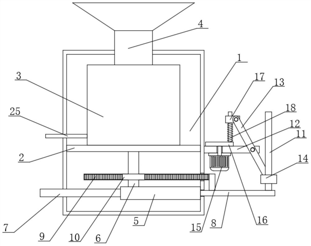
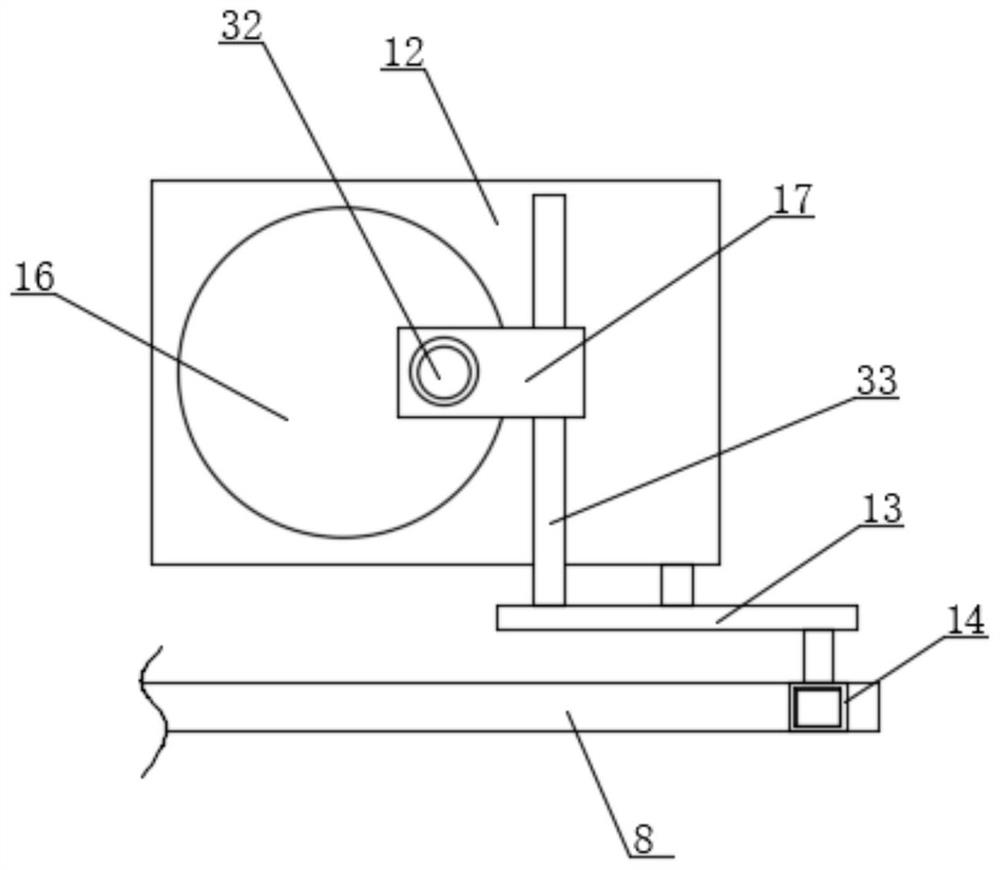
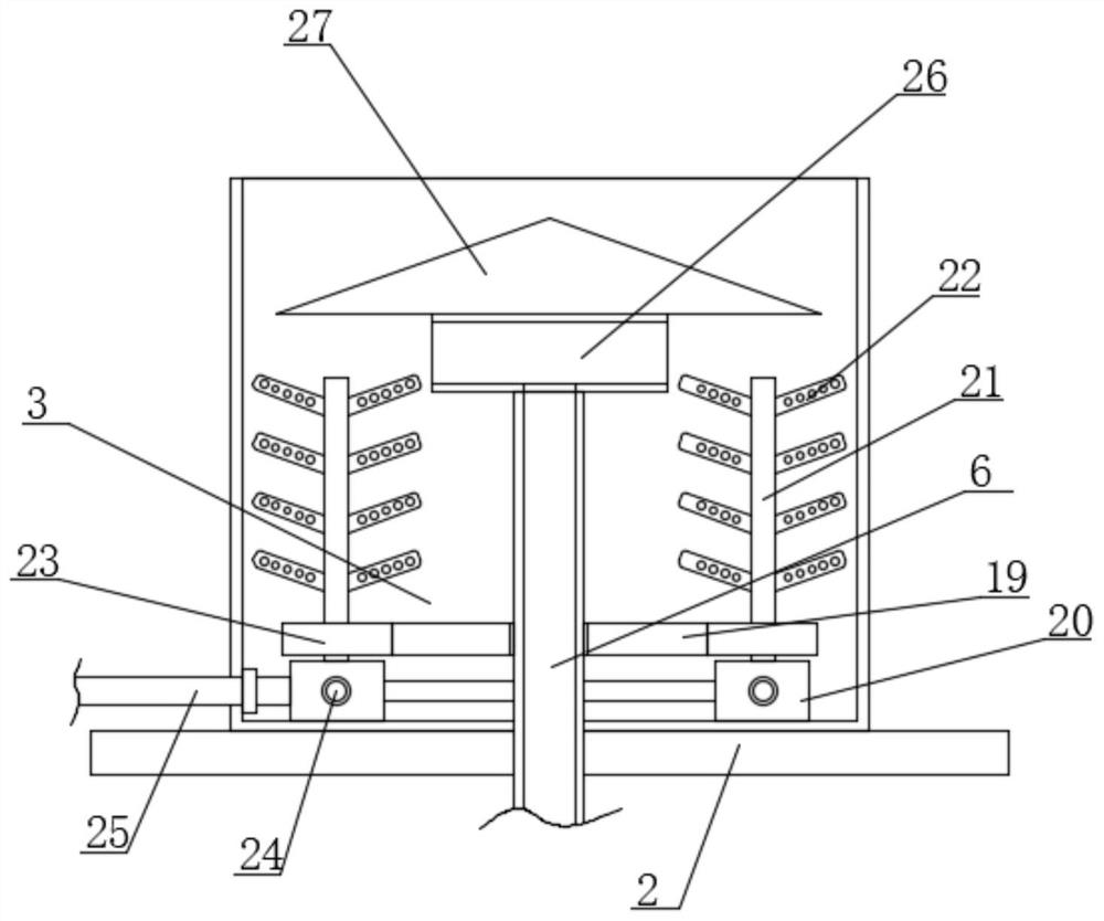
[0032] refer to Figure 1-7, In this embodiment, a cutting fluid cooling device for a five-axis CNC machine tool is proposed, including an installation box 1, a support plate 2 is fixedly installed on the inner wall of the installation box 1, and the support plate 2 can be used to stably support the cooling box 3 , and a cooling box 3 is fixedly installed on the top of the support plate 2, and a plurality of cooling components are installed in the cooling box 3. The cooling components can be used to cool down the cooling liquid, and a conical tube is fixedly installed on the top inner wall of the installation box 1. 4. Using the large opening area of ​​the conical pipe 4, the cooling liquid can be conveniently collected into the cooling box 3, and the top of the conical pipe 4 extends to the top of the installation box 1, and the bottom inner wall of the cooling box 3 rotates on the inner wall. A rotating pipe 6 is connected, and the rotating pipe 6 is connected with a plurali...

Embodiment 2

[0037] On the basis of the first embodiment, the difference of this embodiment is that the infusion assembly includes the installation cover 5, the first check valve 29, the second check valve 30 and the transmission rod 8, and the installation cover 5 is fixedly installed in the installation box On the bottom inner wall of the right side of 1, the installation cover 5 can provide a good airtight environment for the principle of negative pressure suction. The right end of 7 extends into the installation cover 5 and is sealed and fixedly connected with the left inner wall of the installation cover 5. The first one-way valve 29 is fixedly installed at the bottom end of the rotating pipe 6, and the second one-way valve 30 is fixedly installed at the liquid outlet. At the right end of the pipe 7, the first check valve 29 and the second check valve 30 can realize the directional flow of the cooling liquid, and can generate the necessary suction force to facilitate the transportation...


PUM


Abstract

The invention belongs to the field of numerical control machine tools, in particular to a cutting fluid cooling device for a five-axis numerical control machine tool. In view of the existing problems of inconvenient centralized recovery of the cooling fluid and inability to effectively cool the cooling fluid, the following scheme is now proposed: It includes an installation box, a support plate is fixedly installed on the inner wall of the installation box, and a cooling box is fixedly installed on the top of the support plate, a plurality of cooling components are installed in the cooling box, and the top inner wall of the installation box is fixed A conical pipe is installed, and the top of the conical pipe extends to the top of the installation box, and a rotating pipe is rotatably connected to the bottom inner wall of the cooling box. The present invention can realize the functions of centralized collection, rapid cooling and circulating output of the cooling liquid In this way, when the workpiece is processed by the CNC machine tool, the workpiece can be stably cooled and cooled, and the coolant can be prevented from splashing around, so the waste of the coolant can be avoided, so it has good economical practicability.

Description

technical field [0001] The invention relates to the technical field of numerical control machine tools, in particular to a cutting fluid cooling device for a five-axis numerical control machine tool. Background technique [0002] Five-axis linkage CNC machine tool refers to a CNC machine tool that has at least five coordinate axes (three linear coordinates and two rotational coordinates), and can coordinate movements for processing at the same time under the control of a computer numerical control (CNC) system. Machine tools with high technological content and high precision are specially used to process complex curved surfaces, which have a pivotal impact on a country's aviation, aerospace, military, scientific research, precision instruments, high-precision medical equipment and other industries. [0003] When the existing coolant is used to cool the workpiece, the workpiece is often in a rotating state, causing the cooling fluid to perform centrifugal motion and splash ar...

Claims


Application Information

Patent Timeline
Patent Type & Authority Patents(China)
IPC IPC(8): B23Q11/10
CPCB23Q11/10Y02P70/10
Inventor 林建新罗田
Owner 广州通发智能装备股份有限公司
Why Eureka
Try Eureka