Air exhaust module and whole-house regional fresh air replacement system
- Summary
- Abstract
- Description
- Claims
- Application Information
AI Technical Summary
Problems solved by technology
Method used
Image
Examples
Embodiment 1
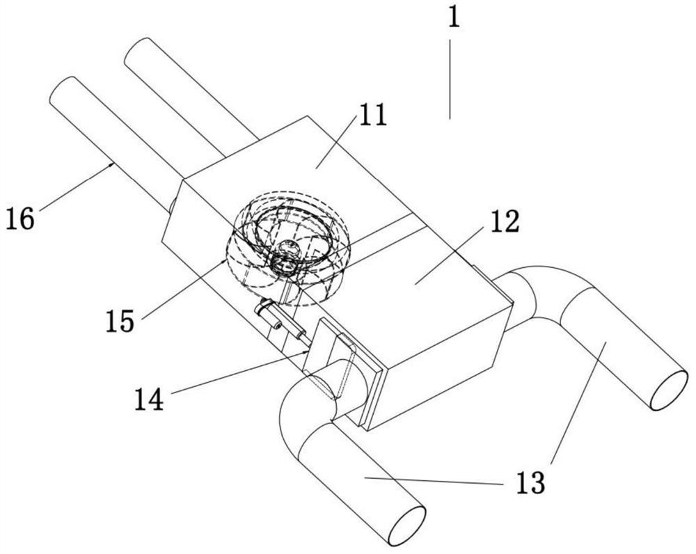
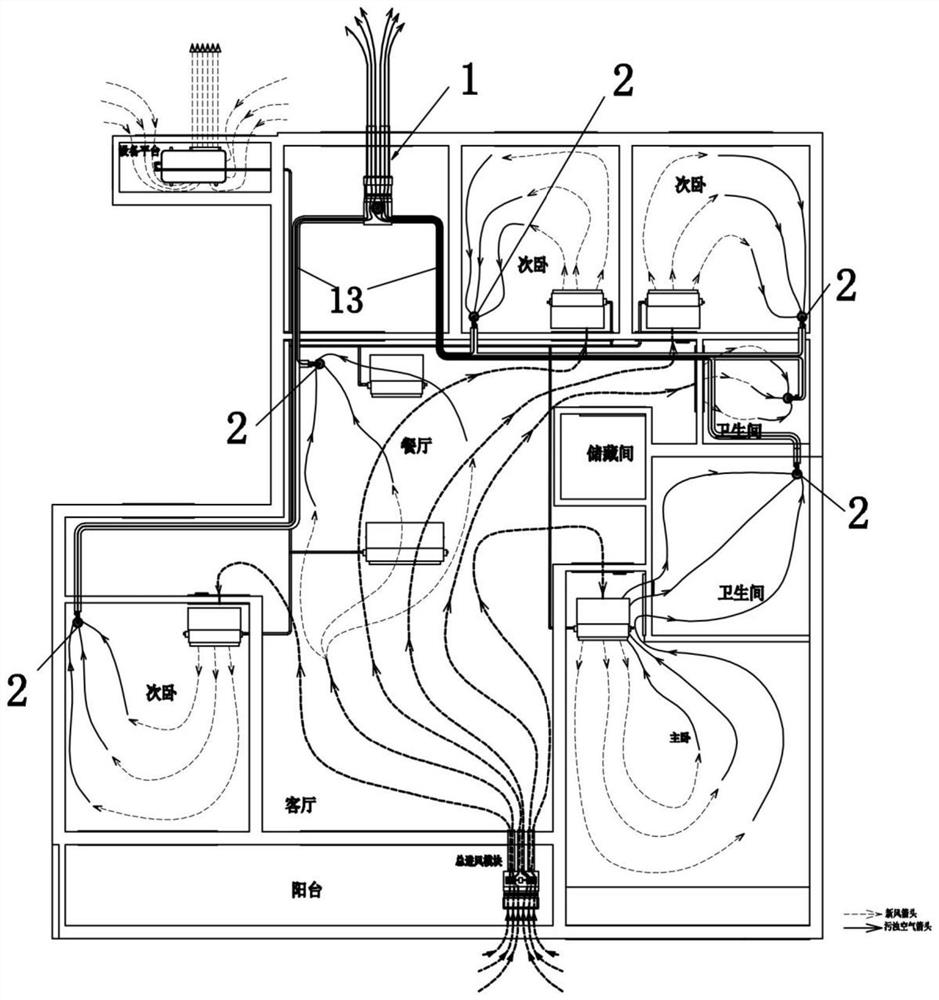
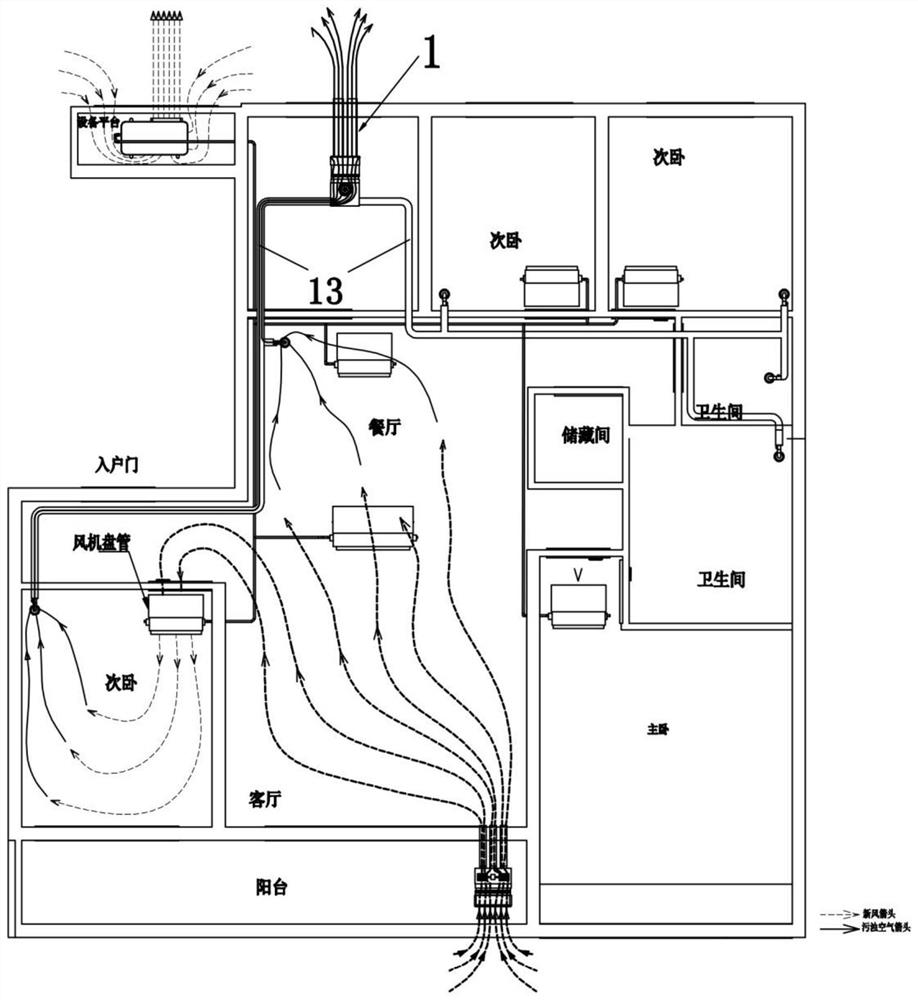
[0054] Please refer to Figure 2 to Figure 4 , a fresh air replacement system in sub-areas for the whole house, applied to room groups, the room group includes a plurality of rooms and a public space connected to each room, and the plurality of rooms may specifically include a study room, a bedroom, a living room, a dining room, a bathroom, and a kitchen , storage room, etc., the public space can be aisle. The system includes the above-mentioned exhaust module 1, and the exhaust module 1 is arranged on the ceiling or wall of a room or public space. The air exhaust module 1 includes a housing, which is divided into an air inlet chamber 12 and an air exhaust chamber 11 connected to each other. An exhaust fan 15 is arranged in the air exhaust chamber 11, and at least one exhaust fan 15 is arranged on the air exhaust chamber 11. A main exhaust pipe 16 is arranged on the air outlet, and the air outlet of the exhaust fan 15 communicates with the atmosphere outside the group of room...
Embodiment 2
[0065] The air inlet cavity 12 of the exhaust module 1 of Embodiment 1 is provided with two air inlets, and the two air inlets are respectively connected to a branch exhaust pipe 13, that is, the exhaust module 1 has two air outlets with opening and closing dampers 14. The branch exhaust duct 13, embodiment 1 divides all the rooms into two areas, one branch exhaust duct 13 corresponds to a room in one area, and the return air duct 2 of the room in each area is connected with the corresponding branch exhaust duct respectively. Tube 13 communicates.
[0066] The difference between this embodiment and Embodiment 1 is that please refer to Figure 5 , the air inlet chamber 12 of the exhaust module 1 is provided with three air inlets, and the three air inlets are respectively connected to a branch exhaust pipe 13, that is, the exhaust module 1 has three branch rows with opening and closing dampers 14. The air ducts are sequentially the first branch exhaust duct 13', the public spac...
Embodiment 3
[0070] This embodiment differs from Embodiment 1 and Embodiment 2 in that, in the exhaust module 1 of this embodiment, the exhaust fan 15 is separated from the air inlet chamber 12, please refer to Image 6 , that is, the air inlet chamber 12 and the air exhaust chamber 11 are separated, and the air inlet chamber 12 and the air exhaust chamber 11 are connected by a connecting pipe 17 .
[0071] In this embodiment, after the exhaust fan 15 is separated from the air inlet chamber 12, the exhaust fan 15 can be arranged near the outer wall, and the air inlet chamber 12 can be arranged in the house cover at a distance from a plurality of branch exhaust pipes 13 respectively. The nearest position of the multiple connected ventilation areas is also a suitable position where the air outlets of multiple branch exhaust pipes 13 gather. This embodiment can disperse the problem of over-concentration of components in the exhaust module 1, increase the flexibility of setting the exhaust mod...
PUM
 Abstract
Description
Claims
Application Information
 - R&D
- Intellectual Property
- Life Sciences
- Materials
- Tech Scout
- Unparalleled Data Quality
- Higher Quality Content
- 60% Fewer Hallucinations
Browse by: Latest US Patents, China's latest patents, Technical Efficacy Thesaurus, Application Domain, Technology Topic, Popular Technical Reports.
© 2025 PatSnap. All rights reserved.Legal|Privacy policy|Modern Slavery Act Transparency Statement|Sitemap|About US| Contact US: help@patsnap.com


