Supercharge Your Innovation With Domain-Expert AI Agents!

Incinerator inlet furnace wall mounting structure and construction method

An installation structure and incinerator technology, applied in the field of incinerators, can solve problems such as cracking and falling off of furnace walls, increase maintenance costs, increase incineration costs, etc., and achieve the effect of avoiding tilting

Active Publication Date: 2021-11-26
JIANGSU YIHUAN GROUP
View PDF9 Cites 0 Cited by
  • Summary
  • Abstract
  • Description
  • Claims
  • Application Information

AI Technical Summary

Problems solved by technology

[0003] However, because the moisture content in the garbage is relatively high, reaching 30-40%, the garbage will undergo rapid expansion and shrinkage fusion under high temperature incineration, which will easily cause the furnace wall to crack and fall off and lose its due effect. Frequent maintenance of the incinerator is required. Increase the cost of incineration, and in the later maintenance, due to the volume and weight of the garbage inlet furnace wall, the maintenance is inconvenient, further increasing the maintenance cost

Method used


Image

  • Incinerator inlet furnace wall mounting structure and construction method
  • Incinerator inlet furnace wall mounting structure and construction method
  • Incinerator inlet furnace wall mounting structure and construction method

Examples


Embodiment 1

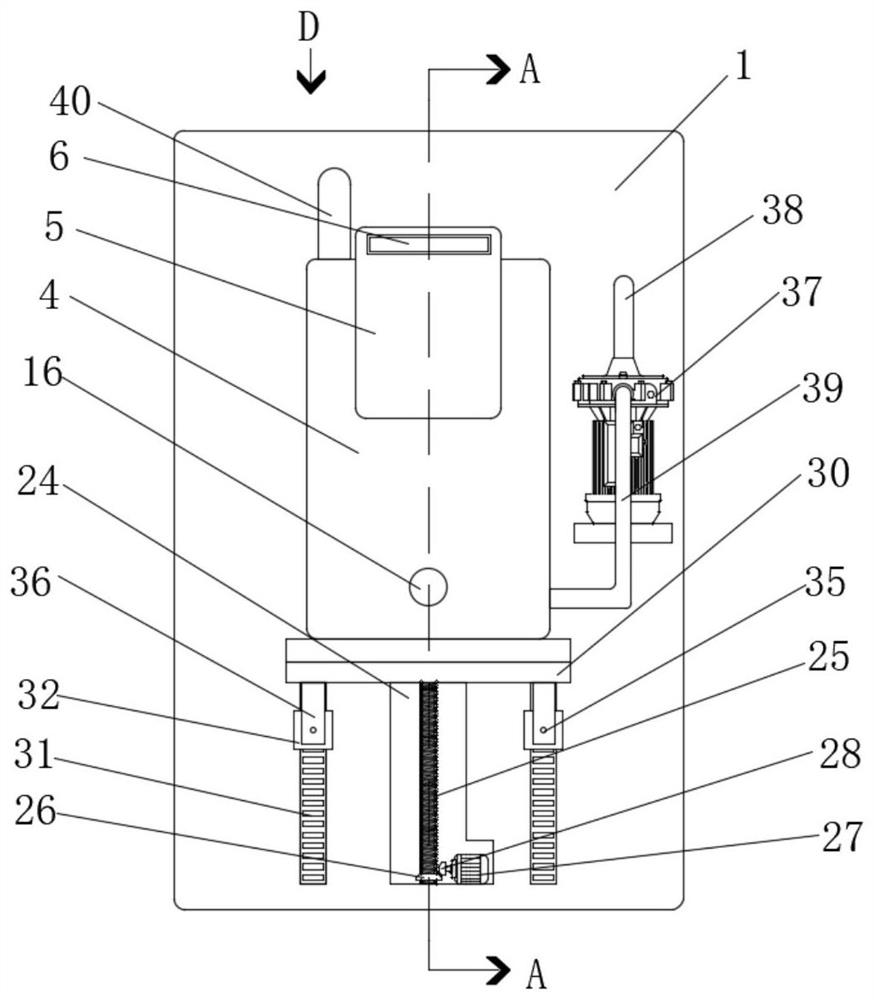
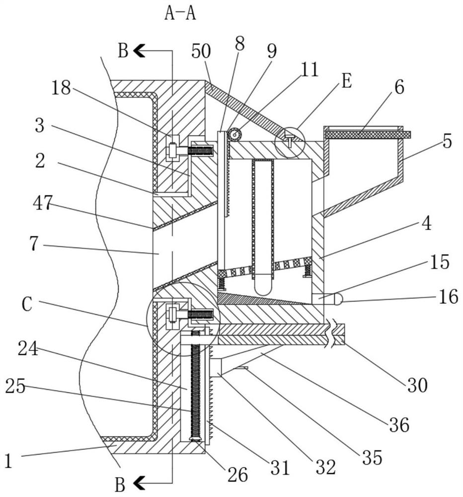
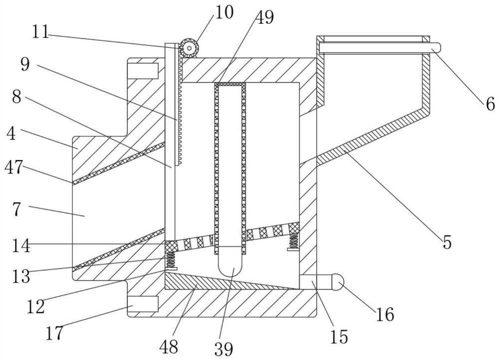
[0040] refer to Figure 1-7 , an incinerator inlet furnace wall installation structure, including an incinerator 1, a rectangular hole 2 and a rectangular groove 3 connected to each other are provided on one side of the incinerator 1, and the same inlet furnace 4 is arranged in the rectangular hole 2 and the rectangular groove 3 , the incinerator 1 is provided with a fixing assembly for fixing the incinerator 1 and the inlet furnace 4, and the side of the inlet furnace 4 away from the incinerator 1 is provided with a connected feed hopper 5, and the feed hopper 5 is slidingly connected with The baffle plate 6, the inlet furnace 4 is provided with a filter assembly for drying the garbage in the inlet furnace 4, the inlet furnace 4 is provided with a plurality of threaded holes 17 on the side near the rectangular groove 3, and the incinerator 1 is provided with a filter assembly for drying the garbage in the inlet furnace 4. The supporting assembly for supporting the bottom of t...

Embodiment 2

[0051] refer to Figure 1-8 , an incinerator inlet furnace wall installation structure, including an incinerator 1, a rectangular hole 2 and a rectangular groove 3 connected to each other are provided on one side of the incinerator 1, and the same inlet furnace 4 is arranged in the rectangular hole 2 and the rectangular groove 3 , the incinerator 1 is provided with a fixing assembly for fixing the incinerator 1 and the inlet furnace 4, and the side of the inlet furnace 4 away from the incinerator 1 is provided with a connected feed hopper 5, and the feed hopper 5 is slidingly connected with The baffle plate 6, the inlet furnace 4 is provided with a filter assembly for drying the garbage in the inlet furnace 4, the inlet furnace 4 is provided with a plurality of threaded holes 17 on the side near the rectangular groove 3, and the incinerator 1 is provided with a filter assembly for drying the garbage in the inlet furnace 4. The supporting assembly for supporting the bottom of t...


PUM


Abstract

The invention discloses an incinerator inlet furnace wall mounting structure and a construction method, and provides the following scheme. One side of an incinerator is provided with a rectangular hole and a rectangular groove which communicate with each other, the same inlet furnace is arranged in the rectangular hole and the rectangular groove, a fixing assembly used for fixing the incinerator and the inlet furnace is arranged in the incinerator, the side, away from the incinerator, of the inlet furnace is provided with a feeding hopper communicating with the inlet furnace, and a baffle is glidingly connected into the feeding hopper. The structure is simple, a stepping motor is started to drive a second bevel gear to rotate, the inlet furnace can be driven to move upwards, the inlet furnace can be positioned through a clamping plate, the inlet furnace conveniently enters the rectangular groove in the later period, and the inlet furnace and the incinerator are fixed; in addition, hot air in the incinerator is conveyed into the inlet furnace through a sucking pump to dry garbage, and it is avoided that a large amount of water is contained in the garbage to affect later-stage garbage incineration.

Description

technical field [0001] The invention relates to the technical field of the incinerator field, in particular to an installation structure and a construction method for an inlet wall of an incinerator. Background technique [0002] The garbage incinerator is a device for incinerating garbage. The garbage burns in the furnace and becomes waste gas, which enters the secondary combustion chamber, burns completely under the forced combustion of the burner, and then enters the spray dust collector. After dust removal, it is discharged into the atmosphere through the chimney , the garbage incinerator is composed of four major systems: garbage pretreatment system, incineration system, smoke biochemical dust removal system and gas generator (auxiliary ignition and incineration), integrating automatic feeding, sieving, drying, incineration, ash cleaning, dust removal, automatic control In one, the garbage incinerator is a kind of harmless treatment equipment commonly used in the harmle...

Claims


Application Information

Patent Timeline
IPC IPC(8): F23G5/44F23M5/04
CPCF23G5/44F23G5/04F23M5/00F26B21/00Y02E20/12
Inventor 杭鑫杭俊亮阚俊杰李薇
Owner JIANGSU YIHUAN GROUP
Features
  • R&D
  • Intellectual Property
  • Life Sciences
  • Materials
  • Tech Scout
  • Unparalleled Data Quality
  • Higher Quality Content
  • 60% Fewer Hallucinations
Learn More