
Doubly-fed wind generator slip ring chamber cooling structure

A technology for wind turbines and cooling structures, which is applied in wind power generation, cooling/ventilation devices, electrical components, etc., can solve the problems of increased wind resistance, troublesome maintenance, and increased number of groups, and can reduce the eddy current loss of the wind path, connect the Easy installation and good construction technology

Pending Publication Date: 2021-11-26
CRRC XIAN YONGE JIELI WIND ENERGY CO LTD
View PDF0 Cites 1 Cited by
  • Summary
  • Abstract
  • Description
  • Claims
  • Application Information

AI Technical Summary

Problems solved by technology

[0002] The doubly-fed wind turbine adopts a wound rotor structure. The rotor side is connected to the inverter through the slip ring brush frame. During operation, the friction between the slip ring and the carbon brush in the slip ring chamber will cause friction loss, and the contact between the carbon brush and the slip ring will cause friction loss. The voltage drop will cause electrical loss, and the heat generated by the loss will cause the temperature of the slip ring and carbon brush to rise. Excessive temperature will cause premature aging and damage to peripheral components. When the temperature trip limit is reached, it will cause shutdown. Therefore, we must think Ways to cool slip rings and carbon brushes, and take away the generated heat in time
[0003] The existing technical solutions generally use air cooling, one is to install an independent cooling fan on the cover plate of the slip ring chamber to blow air into the slip ring chamber, which increases the cost, increases the electrical wiring, and the wind field control strategy, and the toner blowing caused by it is difficult to clean up and requires maintenance. Trouble; the other is that a fan that rotates with the shaft is installed on the generator shaft, and an air inlet is left on the side plate of the slip ring chamber. The suction generated by the fan continuously draws in the cold air at the air inlet of the slip ring chamber. The hot air flows through the slip ring brush holder, and then exhausts the hot air from the other side of the fan. As the power of the double-fed wind turbine increases, on the one hand, the mechanical loss and electrical loss caused by the slip ring and carbon brush increase. The increase in the number of groups of carbon brushes results in more attachments to the slip ring brush holder and increased wind resistance, which makes the cooling medium flow in the outer peripheral space cavity formed between the brush holder and the slip ring chamber shell, causing the slip ring with the most serious heat to rub against the carbon brush Surface cannot be effectively cooled, the temperature is too high

Method used


Image

  • Doubly-fed wind generator slip ring chamber cooling structure
  • Doubly-fed wind generator slip ring chamber cooling structure
  • Doubly-fed wind generator slip ring chamber cooling structure

Examples


Embodiment 1

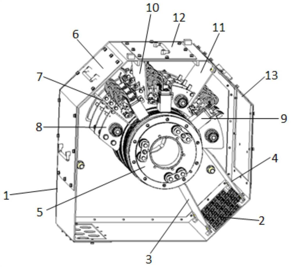
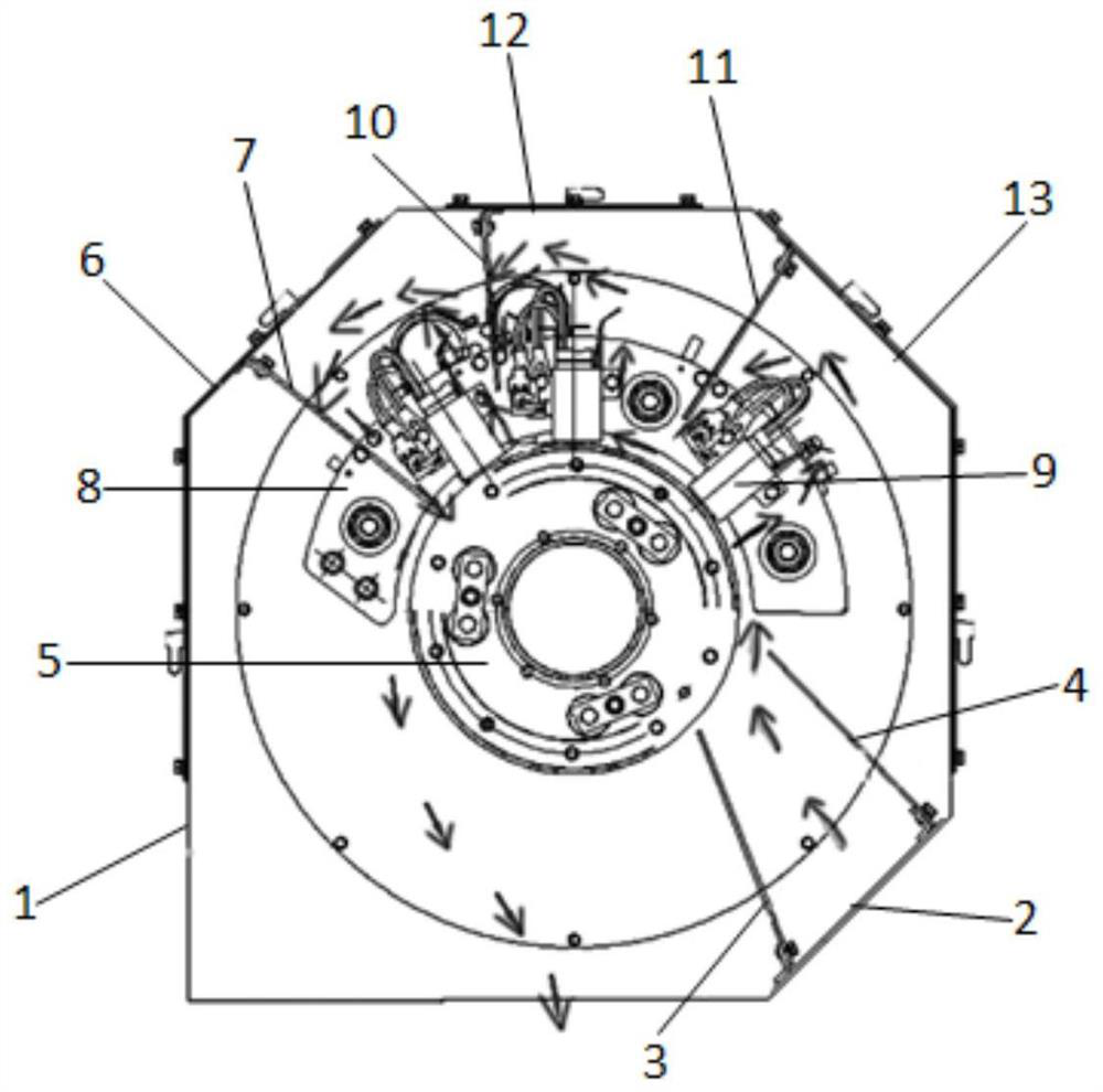
[0040] A double-fed wind power generator slip ring chamber cooling structure, comprising a casing 1 with a polygonal longitudinal section, an air inlet window 2 is fixedly installed on the lower side of the casing, and a first air guide plate 3 and a second air guide plate 3 are installed on the inside of the air inlet window 2. The air duct 4, the first air deflector 3 and the second air deflector 4 form an air channel for guiding the wind entering the slip ring chamber to the surface of the slip ring 5 in the slip ring chamber, and the upper side of the housing 1 is fixedly installed with The first cover plate 6, the inner side of the first cover plate 6 is equipped with a third wind deflector 7, the front edge of the third wind deflector 7 extends into the brush holder 8 of the slip ring chamber, and the rear end surface of the housing 1 is fixedly installed There is a back plate, and an air outlet hole is arranged under the back plate, and a cooling medium is formed between...

Embodiment 2

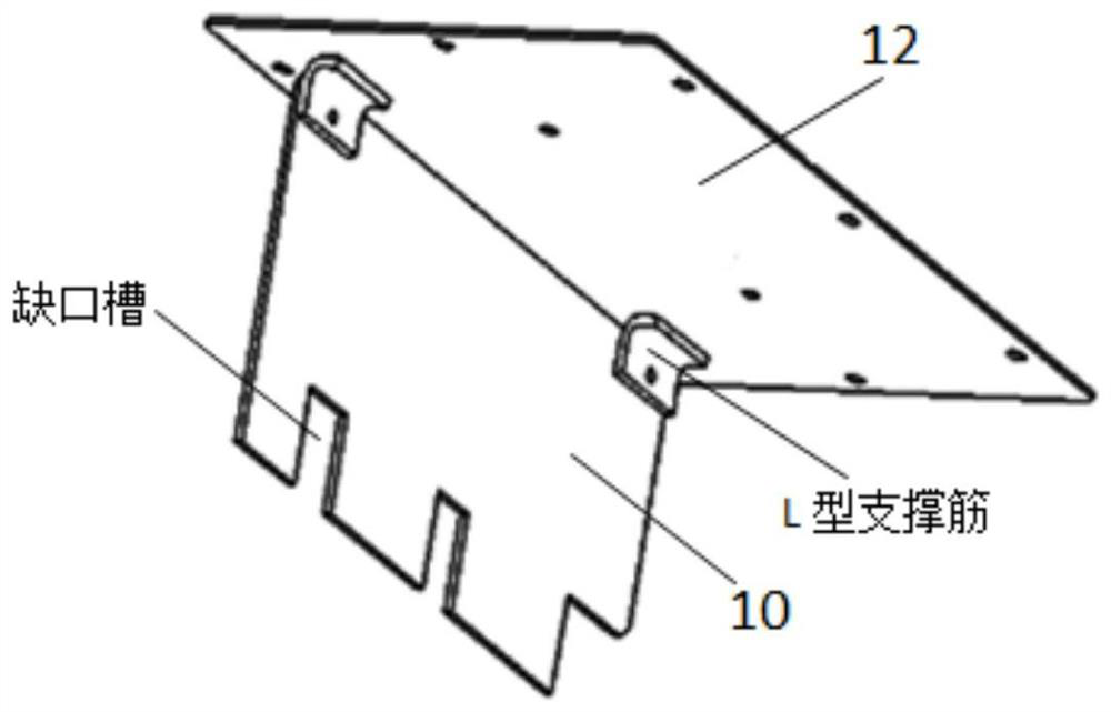
[0042] Such as Figure 1-2 As shown, the present invention provides a double-fed wind power generator slip ring chamber cooling structure, including a polygonal housing 1 with a longitudinal section, and an air inlet window 2 is fixedly installed under the side of the housing, and the inside of the air inlet window 2 is installed There are a first wind deflector 3 and a second wind deflector 4, and an air channel is formed between the first wind deflector 3 and the second wind deflector 4, which is used to guide the wind entering the slip ring chamber to the slip ring chamber The surface of the slip ring 5, the upper side of the housing 1 is fixed with a first cover plate 6, the inner side of the first cover plate 6 is equipped with a third air deflector 7, and the front edge of the third air deflector 7 Part of it extends into the brush holder 8 of the slip ring chamber. A back plate is fixedly installed on the rear end of the housing 1. An air outlet is arranged under the ba...


PUM


Abstract

The invention relates to a doubly-fed wind generator slip ring chamber cooling structure. The cooling structure comprises a shell with a polygonal longitudinal section, an air inlet window is fixedly installed on the lateral lower portion of the shell, a first air guide plate and a second air guide plate are installed on the inner side of the air inlet window, an air channel is formed between the first air guide plate and the second air guide plate, and a first cover plate is fixedly installed on the lateral upper portion of the shell. A third air guide plate is installed on the inner side of the first cover plate, the front edge of the third air guide plate partially extends into the brush frame of the sliding ring chamber, a back plate is fixedly installed on the rear end face of the shell, an air outlet hole is formed below the back plate, and a cooling medium circulation air path is formed among the first air guide plate, the second air guide plate, the third air guide plate, the sliding ring and the brush frame. According to the slip ring chamber cooling structure, the air guide plates are effectively combined with the brush frame ring plate and the slip ring to form a tight air path structure, so that most of the cooling medium flows through the surfaces of each group of carbon brushes and slip rings and does not flow in the peripheral space between the brush holder and the slip ring chamber shell, and the temperature of the slip rings and the carbon brushes is reduced.

Description

technical field [0001] The invention belongs to the technical field of wind power generators, and relates to a cooling structure for a double-fed wind power generator slip ring chamber. Background technique [0002] The doubly-fed wind turbine adopts a wound rotor structure. The rotor side is connected to the inverter through the slip ring brush frame. During operation, the friction between the slip ring and the carbon brush in the slip ring chamber will cause friction loss, and the contact between the carbon brush and the slip ring will cause friction loss. The voltage drop will cause electrical loss, and the heat generated by the loss will cause the temperature of the slip ring and carbon brush to rise. Excessive temperature will cause premature aging and damage to peripheral components. When the temperature trip limit is reached, it will cause shutdown. Therefore, we must think The method is to cool down the slip ring and carbon brush, and take away the generated heat in ...

Claims


Application Information

Patent Timeline
Patent Type & Authority Applications(China)
IPC IPC(8): H02K9/28H02K5/14
CPCH02K9/28H02K5/141Y02E10/72
Inventor 李攀军崔皓何庆峰刘新峰钟绍辉朱铭锴
Owner CRRC XIAN YONGE JIELI WIND ENERGY CO LTD
Learn More