Planing machine capable of conveniently planing any plane of material

A plane and planing technology, which is applied in the field of machine tools, can solve the problems of inability to deal with processing waste and the inability of the planer to adjust the processing plane conveniently, and achieve the effects of easy collection, easy planing, and convenient replacement

Inactive Publication Date: 2021-11-30
宋淑兰
View PDF0 Cites 2 Cited by
  • Summary
  • Abstract
  • Description
  • Claims
  • Application Information

AI Technical Summary

Problems solved by technology

[0002] Planers are commonly used machine tools for mechanical processing. Traditional planers can

Method used


Image

  • Planing machine capable of conveniently planing any plane of material
  • Planing machine capable of conveniently planing any plane of material
  • Planing machine capable of conveniently planing any plane of material

Examples


specific Embodiment approach 1

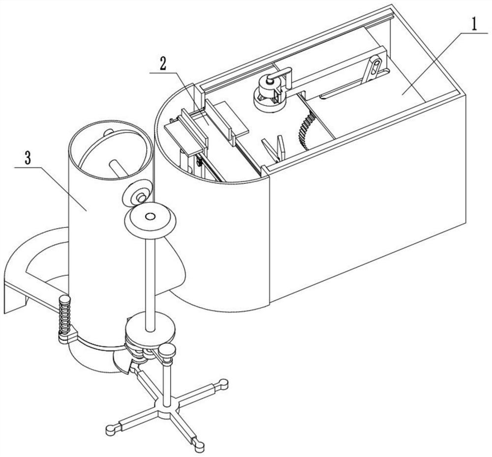
[0029] Combine below Figure 1-15 Describe this embodiment, a planer that is convenient for planing any plane of materials, including a planing assembly 1, a clamping assembly 2 and an iron filings pressing assembly 3, the planing assembly can drive the cutter to reciprocate to plan the material , the tool is easy to replace, the clamping assembly can clamp any shape of material, the processing plane can be adjusted conveniently, the position of the material can be adjusted according to the reciprocation of the tool, and it is easy to plan. Chips are collected and pressed into blocks, which is convenient for collection and processing, and avoids waste of resources.

specific Embodiment approach 2

[0030] Combine below Figure 1-15Describe this embodiment, this embodiment will further explain Embodiment 1, place the material to be planed in the angle adjustment disc 2-4, turn the knob 2-13, the knob 2-13 drives the two-way threaded shaft 2-14 to rotate, and the two-way The threaded shaft 2-14 is axially limited by the intermittent slide plate 2-11, and the two-way threaded shaft 2-14 is provided with two threads with opposite directions of rotation. The two clamping plates 2-12 are threaded, and the two-way threaded shaft 2-14 drives the two clamping plates 2-12 to approach each other to clamp the material. The hydraulic cylinder 2-1 is connected to the hydraulic system, and the hydraulic system can control the hydraulic pressure separately. Cylinder 2-1 oil injection and oil output, the hydraulic system respectively controls the oil injection and oil output to the hydraulic cylinders 2-1 on both sides to drive the telescopic rod 2-2 to shrink and stretch, and the height...

specific Embodiment approach 3

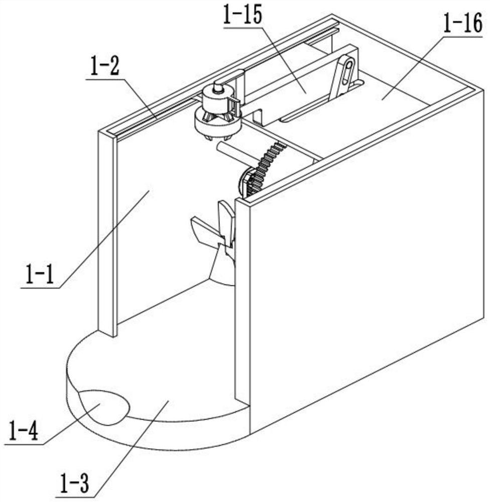
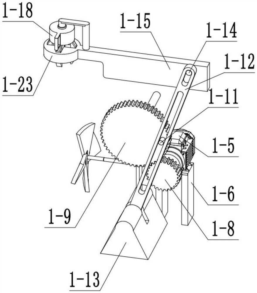
[0031] Combine below Figure 1-15 Describe this embodiment. This embodiment will further explain Embodiment 1. After the clamping is completed, place the tool between the four tool holders 1-21, turn the handle 1-17, and the handle 1-17 drives the threaded sleeve 1-18 Turn, the threaded sleeve 1-18 moves downward under the action of threaded connection with the threaded shaft 1-19, and the threaded sleeve 1-18 slides inwardly along the clamp sliding chamber 1-23 while moving the four tool holders 1-21 , the shrapnel 1-22 shrinks, the four tool holders 1-21 clamp the tool, turn on the motor 1-5, the motor 1-5 drives the motor shaft 1-7 to rotate, the motor shaft 1-7 drives the gear I 1-8 to rotate, the gear Ⅰ1-8 drives gear Ⅱ1-9 to rotate, gear Ⅱ1-9 drives gear Ⅱ bump 1-11 to rotate, gear Ⅱ bump 1-11 drives swing connecting rod 1-12 to rotate around the hinge shaft with connecting rod lug 1-13 Reciprocating swing, swing connecting rod 1-12 drives swing bump 1-14 to move, swing...


PUM


Abstract

The invention relates to the field of machine tools, in particular to a planing machine capable of conveniently planing any plane of a material. When the planing machine is used for machining, a common machine tool is used, a traditional planing machine cannot conveniently adjust the machining plane, and machining waste scraps cannot be treated. The planing machine solves the problems, a planing combination can drive a cutter to do reciprocating motion to plane the material, the cutter is convenient to replace, a clamping combination can clamp the material in any shape, the machining plane can be conveniently adjusted, the position of the material can be adjusted according to the reciprocating motion of the cutter, planing is facilitated, a scrap iron pressing combination can collect scrap iron generated by planing and press the scrap iron into blocks, collection and treatment are facilitated, and resource waste is avoided.

Description

technical field [0001] The invention relates to the field of machine tools, in particular to a planer which is convenient for planing any plane of materials. Background technique [0002] Planers are commonly used machine tools for mechanical processing. Traditional planers cannot easily adjust the processing plane and cannot handle processing waste. This equipment solves the above problems. Contents of the invention [0003] The purpose of the present invention is to provide a planer which is convenient for planing any plane of materials, and can plan parts automatically and conveniently. [0004] The purpose of the present invention is achieved through the following technical solutions: [0005] A planer that is convenient for planing any plane of materials, comprising a planing assembly, a clamping assembly and an iron filings pressing assembly, characterized in that: the clamping assembly, the iron filings pressing assembly are all combined with the planing assembly ...

Claims


Application Information

Patent Timeline
IPC IPC(8): B23D1/18B23D1/20B23D7/00B23D13/00B30B9/32
CPCB23D1/18B23D1/20B23D7/00B23D13/005B30B9/32
Inventor 宋淑兰
Owner 宋淑兰
Why Eureka
Try Eureka