Manufacturing method of wafer

A manufacturing method and wafer technology, applied in the field of wafer manufacturing, can solve problems such as being unfavorable to mass production, increasing process complexity, increasing production costs, and the like

Pending Publication Date: 2021-11-30
深圳市大族半导体装备科技有限公司
View PDF4 Cites 3 Cited by
  • Summary
  • Abstract
  • Description
  • Claims
  • Application Information

AI Technical Summary

Problems solved by technology

The spin-coating process of glue increases the complexity of the process, which is not conducive to mass production
In addition, liquid nitrogen refrigeration is used in the above separation scheme, and liquid nitrogen as a consumable will increase additional production costs
At the same time, the introduction of refrigeration devices will also make the equipment manufacturing process more complicated
The above problems limit the application of this scheme in industrial production

Method used

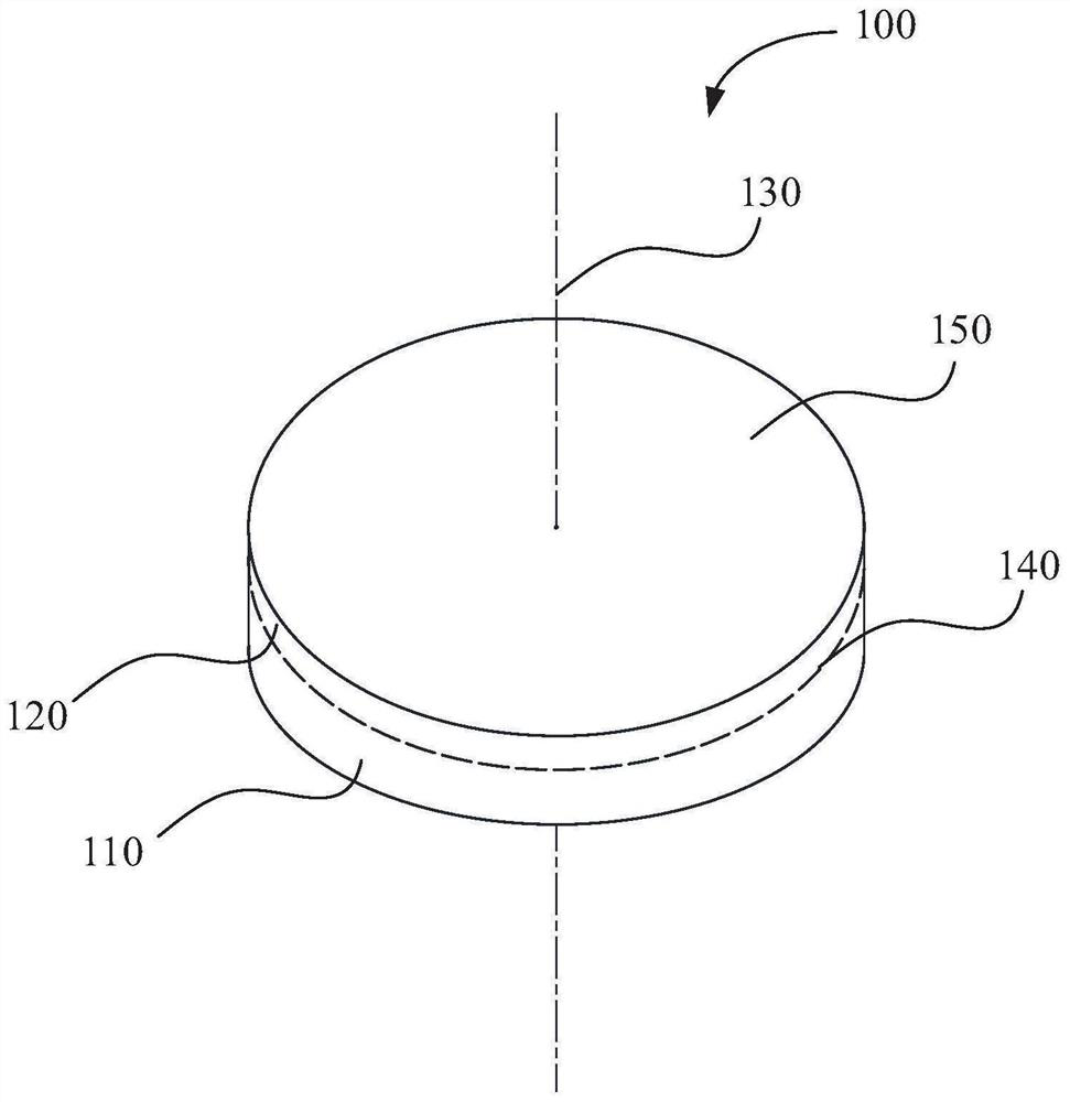
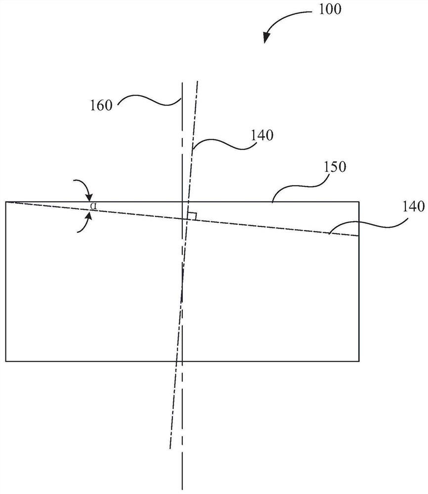
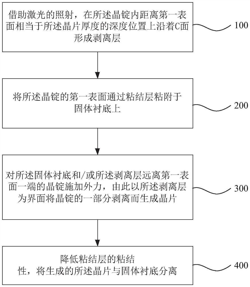

Image

  • Manufacturing method of wafer
  • Manufacturing method of wafer
  • Manufacturing method of wafer

Examples


Embodiment Construction

[0051] In order to make the technical problems, technical solutions and beneficial effects to be solved by the present application clearer, the present application will be further described in detail below in conjunction with the accompanying drawings and embodiments. It should be understood that the specific embodiments described here are only used to explain the present application, and are not intended to limit the present application.

[0052]It should be noted that when a metastructure is said to be "fixed on" or "set on" another metastructure, it can be directly on the other metastructure or indirectly on the other metastructure. When a metastructure is referred to as being "connected to" another metastructure, it can be directly connected to the other metastructure or indirectly connected to the other metastructure.

[0053] It is to be understood that the terms "length", "width", "top", "bottom", "front", "rear", "left", "right", "vertical", "horizontal", "top" , "bot...


PUM

PropertyMeasurementUnit
wavelengthaaaaaaaaaa

Abstract

The invention provides a manufacturing method of a wafer. The manufacturing method comprises the following steps of: forming a stripping layer along a C surface at a depth position equivalent to the thickness of the wafer from a first surface in a crystal ingot by virtue of laser irradiation; adhering the first surface of the crystal ingot to a solid substrate through an adhesive layer; applying an external force to the solid substrate and / or the crystal ingot at one end, far away from the first surface, of the stripping layer, so that the crystal ingots at two ends of the stripping layer generate relative motion, and a part of the crystal ingot is stripped by taking the stripping layer as an interface to generate the wafer; and reducing the cohesiveness of the adhesive layer, and separating the generated wafer from the solid substrate. According to the manufacturing method, the stripping process of the crystal ingot is simple and reliable, the production cost is reduced, and the production efficiency is improved.

Description

technical field [0001] The present application belongs to the technical field of semiconductor element manufacturing, and more specifically, relates to a wafer manufacturing method. Background technique [0002] In the semiconductor industry, wafers of materials such as silicon carbide (SiC), silicon (Si), sapphire (Al2O3), glass, etc. are usually used as substrates for preparing devices. The traditional wafer preparation method is to peel the ingot into pieces using wire saw cutting or "cold separation". [0003] However, there is serious material loss in the way of wire saw cutting, and the slicing process will cause most (70-80%) of the crystal ingot to be discarded. Especially for high-hardness SiC materials (Mohs hardness 9.5), the wire sawing method not only consumes a lot of material, but also has many problems such as low efficiency, serious tool wear and environmental pollution, which seriously restricts the development of the SiC industry. [0004] In the "cold s...

Claims


Application Information

Patent Timeline
Patent Type & Authority Applications(China)
IPC IPC(8): B23K26/362B23K26/70
CPCB23K26/362B23K26/70
Inventor 李春昊郝宏伟巫礼杰任达仰瑞贺少鹏童灿钊尹建刚高云峰
Owner 深圳市大族半导体装备科技有限公司
Why Eureka
Try Eureka