

Optical lens and imaging equipment
An optical lens and lens technology, applied in the field of imaging lenses, can solve the problems of non-adjustable lenses, low assembly yield, and poor imaging quality, and achieve the goal of shortening the overall length, satisfying miniaturization, and improving manufacturing yield and imaging quality. Effect
- Summary
- Abstract
- Description
- Claims
- Application Information
AI Technical Summary
Problems solved by technology
Method used
Image

Examples
no. 1 example
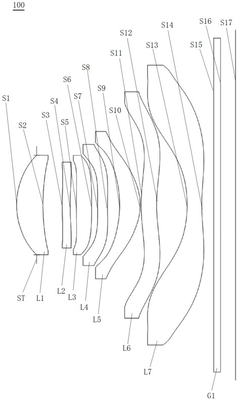
[0078] See figure 1 The schematic structural diagram of the optical lens 100 provided in the first embodiment of the present invention has: a stop ST, a first lens L1, a second lens L2, and a second lens L2, and a first lens L1, a second lens L2. The third lens L3, the fourth lens L4, the fifth lens L5, the sixth lens L6, the seventh lens L7, and the filter G1.
[0079] Among them, the first lens L1 has a positive optical focus, and the side surface S1 of the first lens is a convex surface, and the image side surface S2 of the first lens is a concave surface;
[0080] The second lens L2 has a negative optical focus, and the side surface S3 of the second lens is a convex surface at the near-optical axis, and the image side surface S4 of the second lens is a concave surface at the near-optical axis;
[0081] The third lens L3 has a positive optical focus, and the side surface S5 of the third lens is a convex surface at the near-optical axis, and the image side surface S6 of the thir...
no. 2 example
[0095] like Figure 5 , The optical lens 200 provided in the structural diagram of the present embodiment, the optical lens 200 of the present embodiment is substantially the same as the above-described first embodiment, the main difference is that the radius of curvature of each lens surface type aspherical coefficients, the thickness vary.
[0096] Specifically, the optical lens according to this embodiment 200 of the design parameters shown in Table 3.
[0097] table 3
[0098]
[0099] In this embodiment, each lens in the optical lens 200 Aspherical surface data shown in Table 4.
[0100] Table 4
[0101]
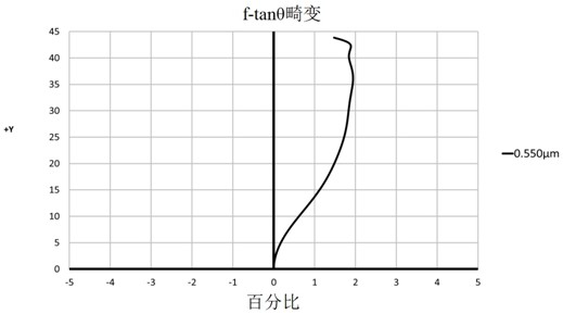
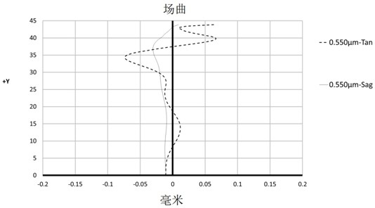
[0102] Please refer to Image 6 , Figure 7 with Figure 8 , Respectively, f-tanθ graph showing distortion of the optical lens 200, the paraxial field curvature graph, the vertical axis of the graph shown in color, from Image 6 Controlling the optical distortion can be seen within 2%, indicating that the distortion of the optical lens 200 to obtain good correction; from Fig...
no. 3 example
[0104] like Figure 9 , The optical lens 300 provided in the structural diagram of the present embodiment, the optical lens 300 of the present embodiment, the above-described embodiment is substantially the same as the first embodiment, except that: the third lens of the optical lens 300 in the embodiment of the present embodiment image-side surface S6 is a concave surface at the paraxial, radius of curvature of each lens surface and the type of aspheric coefficient, thickness vary.
[0105] Specifically, the optical lens according to this embodiment 300 of the design parameters shown in Table 5.
[0106] table 5
[0107]
[0108] Embodiment, the optical lens 300 in the parameters of each aspheric lenses are shown in Table 6 embodiment.
[0109] Table 6
[0110]
[0111] Please refer to Figure 10 , Figure 11 with Figure 12 , Respectively, f-tanθ graph showing distortion of the optical lens 300, the paraxial field curvature graph, the vertical axis of the graph shown in color, f...
PUM
 Abstract
Description
Claims
Application Information