Supercharge Your Innovation With Domain-Expert AI Agents!

Releasing mechanism capable of releasing spring ring

A spring coil and lock technology, applied in medical science, surgery, ligation, etc., can solve the problems of long connecting device length, deformation of release rod, steel ball locking, etc., and achieve short locking and releasing mechanism, locking and releasing mechanism. Compact, highly reliable results

Pending Publication Date: 2021-12-03
南京思脉德医疗科技有限公司
View PDF4 Cites 0 Cited by
  • Summary
  • Abstract
  • Description
  • Claims
  • Application Information

AI Technical Summary

Problems solved by technology

This type of connection point is an active connection point, and the moving process will cause the release rod to deform or the steel ball to lock, and the steel ball may cause blood vessel rupture
Also, the long length of this type of coupling can lead to tube kicks during the final stages of the coil delivery process.

Method used


Image

  • Releasing mechanism capable of releasing spring ring
  • Releasing mechanism capable of releasing spring ring
  • Releasing mechanism capable of releasing spring ring

Examples


Embodiment 1

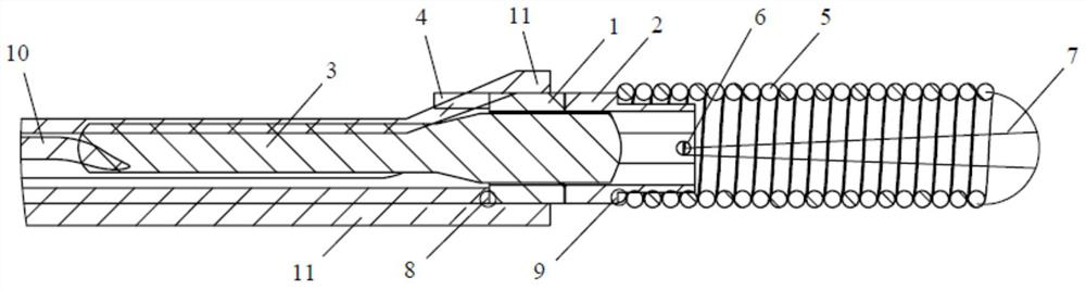
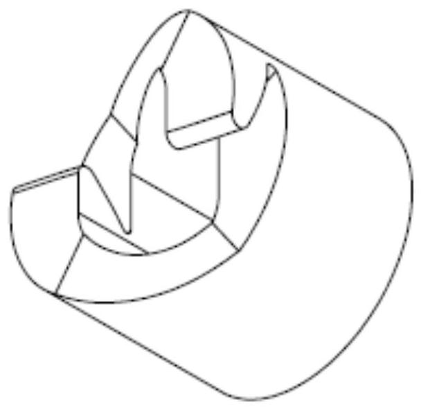
[0057] Such as Figure 2 to Figure 5 As shown, the second end of the first lock 1 has two oblique cuts, the third end of the second lock 2 has oblique cuts matching the second end of the first lock 1, through the oblique cuts, Engage the second end of the first lock 1 and the third end of the second lock 2 to form a flexible connection, and the engagement form is as follows Figure 4 and Figure 5 shown.

[0058] In this embodiment, the pitch of the oblique cuts of the first lock 1 and the second lock 2 can be 0.3 mm, and can be cut out by laser processing.

[0059] The cross-sectional shape of the first through hole of the first lock 1 and the second through hole of the second lock 2 is flat, and the length direction of the flat is an asymmetric structure, that is, a tapered structure, which can also be described as a gradual expansion. structure.

[0060] The cross-sectional shape of the distal section of the fixing pin 3 is a flat shape matching the cross-section of the...

Embodiment 2

[0063] The difference between this embodiment and Embodiment 1 is that the cross-sectional shapes of the first through hole of the first lock 1 and the second through hole of the second lock 2 are circular, but the axis of the first through hole is in line with the second through hole. The axis of a lock 1 is not coincident, and correspondingly, the axis of the second through hole is not coincident with the axis of the second lock 2 .

[0064] The cross-sectional shape of the distal section of the fixing pin 3 is also circular and matches the first through hole. In this embodiment, the axis of the proximal section of the fixing pin 3 coincides with the axis of the push rod 4 , therefore, the axis of the distal section and the axis of the proximal section of the fixing pin 3 do not coincide. There is an included angle between the middle section of the fixing pin 3 and the far section, and the middle section of the fixing pin 3 also plays a position-limiting role, limiting the p...


PUM


Abstract

The invention discloses a releasing mechanism capable of releasing a spring ring. The releasing mechanism comprises a first lock catch, a second lock catch and a fixing pin, wherein the first lock catch is provided with a first end and a second end which are oppositely arranged, the second lock catch is provided with a third end and a fourth end which are oppositely arranged, and the second end of the first lock catch is connected with the third end of the second lock catch; a first through hole is formed in the first lock catch from the first end to the second end, a second through hole is formed in the second lock catch from the third end to the fourth end, and the first through hole and the second through hole are the same in section shape; the fixing pin comprises a near section, a middle section and a far section, and the section shape of the far section of the fixing pin is matched with that of the first through hole; and the fixing pin is configured to prevent relative rotation of the first lock catch and the second lock catch when the far section of the fixing pin is inserted into the first through hole and the second through hole. The releasing mechanism is simple in structure, capable of rapidly locking and releasing the spring coil, high in reliability and good in safety.

Description

technical field [0001] The invention relates to the technical field of delivery devices for medical instruments, in particular to a release mechanism for a release spring coil. Background technique [0002] Hemangioma is a tumor-like protrusion or arteriovenous malformation in the wall of an artery or vein caused by the localized abnormal expansion of the lumen of an artery or vein. The more common one is an intracranial arteriovenous aneurysm. A coil is a medical device used to treat aneurysms. The coil is connected to a stainless steel guide wire and can be fed directly into the aneurysm. With the rapid development of embolic coil products, embolization of aneurysms is a popular treatment method. flow within. The routine process of embolizing aneurysms is to puncture the femoral artery, insert a guide catheter, then send a microcatheter into the parent artery through the guide catheter, and finally send an embolization coil into the aneurysm cavity through the microcathe...

Claims


Application Information

Patent Timeline
IPC IPC(8): A61B17/12
CPCA61B17/12113A61B17/1214A61B2017/1205A61B2017/12054
Inventor 裴世宁章仕忠方晓东
Owner 南京思脉德医疗科技有限公司
Features
  • R&D
  • Intellectual Property
  • Life Sciences
  • Materials
  • Tech Scout
  • Unparalleled Data Quality
  • Higher Quality Content
  • 60% Fewer Hallucinations
Learn More