
Graded stirring type reaction kettle stirrer for chemical machinery

A kettle stirrer, chemical machinery technology, applied in the field of graded stirring reactor stirrer for chemical machinery, can solve the problems of increased heat dissipation, maintenance and service life, large resistance of stirring blades, increased load of rotating motor, etc., to achieve increased mixing Strength and effect, effect of improving stirring efficiency

Inactive Publication Date: 2021-12-03
河南爱维安环科技有限公司
View PDF6 Cites 0 Cited by
  • Summary
  • Abstract
  • Description
  • Claims
  • Application Information

AI Technical Summary

Problems solved by technology

The drug is stirred by the stirring paddle in the reaction kettle, and at the same time, the needle tip of the defoaming needle is used to defoam the bubbles to improve the defoaming effect, and the defoaming needle has a spiral structure, which can accelerate the disturbance of the bubbles suspended on the surface to further improve the defoaming effect. Defoaming effect, but the above-mentioned agitator has more mixing blades. In the initial stage of raw material mixing, the degree of mixing between raw materials is poor, resulting in greater resistance of the raw materials to the stirring blades, and the resistance acts on the rotating shaft of the motor accordingly, resulting in The load of the rotating motor increases significantly, which increases the corresponding problems of heat dissipation, maintenance and service life

Method used


Image

  • Graded stirring type reaction kettle stirrer for chemical machinery
  • Graded stirring type reaction kettle stirrer for chemical machinery
  • Graded stirring type reaction kettle stirrer for chemical machinery

Examples


Embodiment Construction

[0031] The following will clearly and completely describe the technical solutions in the embodiments of the present invention with reference to the accompanying drawings in the embodiments of the present invention. Obviously, the described embodiments are only some, not all, embodiments of the present invention. Based on the embodiments of the present invention, all other embodiments obtained by persons of ordinary skill in the art without making creative efforts belong to the protection scope of the present invention.

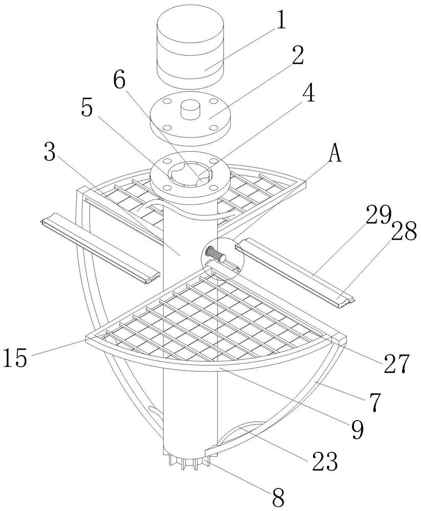
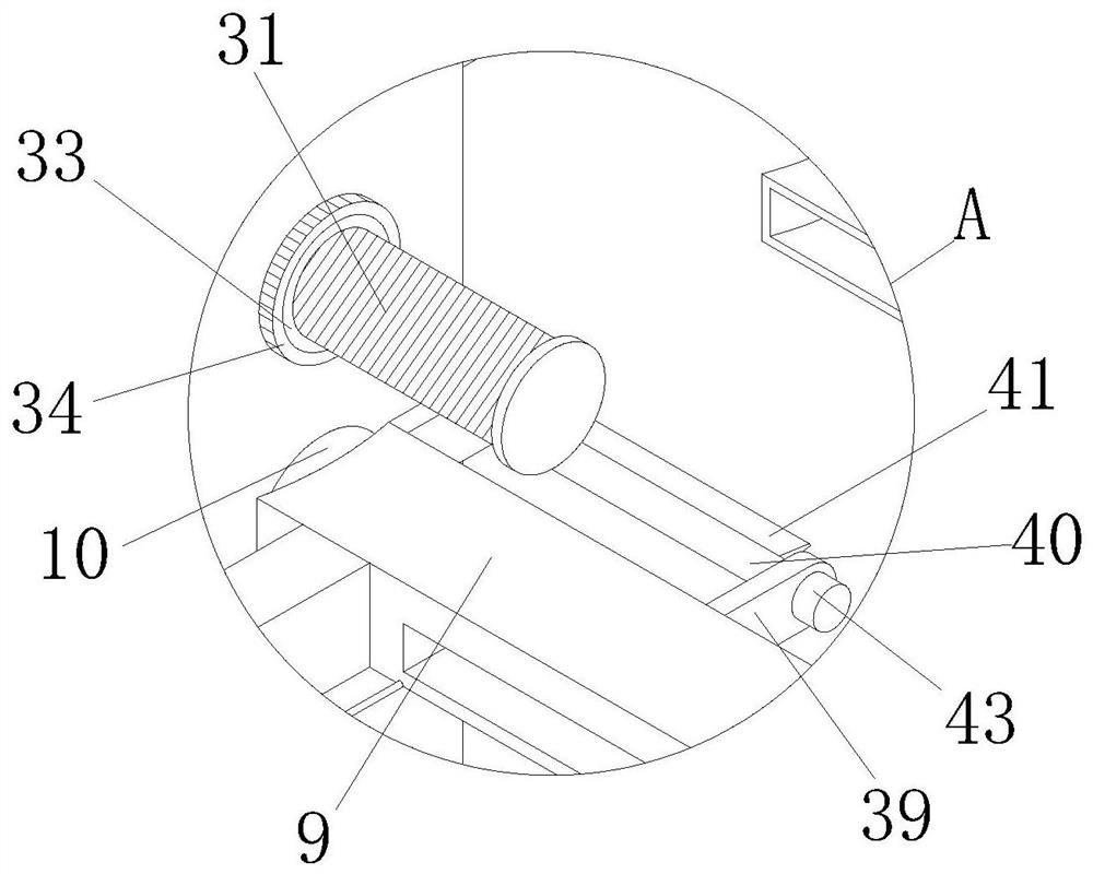
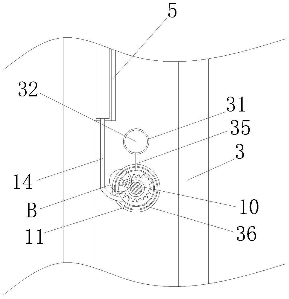
[0032] see Figure 1-7 , a kind of graded agitation type reaction kettle stirrer for chemical machinery, comprises rotating motor 1, and the transmission shaft of rotating motor 1 is fixedly connected with connection plate 2, and the top surface of connection plate 2 is provided with four circular holes in ring shape, and connection plate 2 The drive shaft 3 that is hollowed out in the center is arranged below the bottom of the drive shaft 3, and the top surfa...


PUM


Abstract

The invention relates to the technical field of stirrers, and discloses a graded stirring type reaction kettle stirrer for chemical machinery. The graded stirring type reaction kettle stirrer comprises a rotating motor, a transmission shaft of the rotating motor is fixedly connected with a connecting disc, a driving shaft with a hollow center is arranged below the connecting disc, and a driven shaft is arranged on the inner ring of the driving shaft; stirring plates A are fixedly connected to the bottom ends of the left side and the right side of the driving shaft; the bottom end of the driven shaft protrudes out of the driving shaft, and a plurality of stress sector plates A are fixedly connected to the outer wall of the protruding position at equal intervals; stirring plates B are arranged at the top ends of the faces, corresponding to the driving shaft, of the stirring plates A;through the arrangement of the connecting disc and the driving shaft, when the initial concentration of raw materials in the reaction kettle is high, and after raw materials are preliminarily stirred to a proper dilution degree by using the stirring plate A subjected to smaller resistance, the stirring plate B provided with the stirring shaft A is automatically detected and driven to participate in stirring, so that the situation that the raw materials in the reaction kettle generate larger resistance to the stirring plate B at the initial stage of mixing, so that the load borne by the rotating motor is overlarge is avoided.

Description

technical field [0001] The invention relates to the technical field of stirrers, in particular to a graded stirring type reactor stirrer for chemical machinery. Background technique [0002] Reactors are widely used in the fields of petroleum, chemical industry, rubber, pesticides, dyes, medicine and food. They are pressure vessels used to complete vulcanization, nitration, hydrogenation, alkylation, polymerization, condensation and other processes, such as reactors and reaction pots. , decomposition pot, polymerization kettle, etc. In the reactor, it is necessary to stir, mix or dilute various raw materials, so it is necessary to use the agitator to perform the above operations. [0003] The existing patent No. CN108607481A proposes a pharmaceutical reactor stirrer, which belongs to the field of pharmaceutical equipment. It solves the problem of poor defoaming effect of the existing agitator. The pharmaceutical reactor stirrer includes a stirring shaft and a stirring padd...

Claims


Application Information

Patent Timeline
Patent Type & Authority Applications(China)
IPC IPC(8): B01J19/00
CPCB01J19/0066
Inventor 赵鹏航
Owner 河南爱维安环科技有限公司
Learn More