Phase current acquisition method, device, equipment and system and storage medium

A collection method and phase current technology, which is applied in the direction of measuring devices, voltage/current isolation, and measurement of electrical variables, can solve the problems of Hall current sensors such as high cost, difficulty in implementation, and space vectors falling in unobservable areas, so as to improve Power supply voltage utilization and the effect of increasing output torque

Active Publication Date: 2021-12-03
FOSHAN SHUNDE MIDEA ELECTRONICS TECH CO LTD +1
View PDF17 Cites 4 Cited by
  • Summary
  • Abstract
  • Description
  • Claims
  • Application Information

AI Technical Summary

Problems solved by technology

However, because the space vector falls in the unobservable region when the overmodulation phenomenon occurs, the related method based on a single current sensor to complete the phase current acquisition method is difficult to implement
[0006] Therefore, in the overmodulation area, it is often necessary to use the Hall current sensor to collect the phase current of any two phases of the three-phase motor, so as to obtain the current three-phase current value. However, the high cost of the Hall current sensor increases the cost of three-phase motor control. cost

Method used


Image

  • Phase current acquisition method, device, equipment and system and storage medium
  • Phase current acquisition method, device, equipment and system and storage medium
  • Phase current acquisition method, device, equipment and system and storage medium

Examples


Embodiment Construction

[0050] The application will be further described in detail below in conjunction with the accompanying drawings and embodiments.

[0051] Unless otherwise defined, all technical and scientific terms used herein have the same meaning as commonly understood by one of ordinary skill in the technical field to which this application belongs. The terms used herein in the specification of the application are only for the purpose of describing specific embodiments, and are not intended to limit the application.

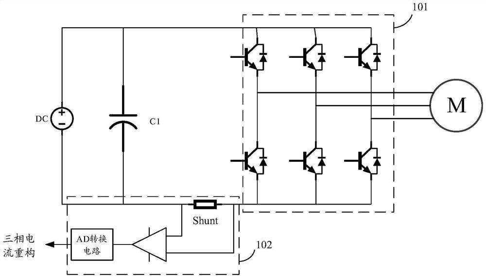
[0052] In related technologies, motor application systems based on bus current acquisition such as figure 1 As shown, the system includes: a motor M, a three-phase bridge inverter 101 , a DC power supply DC and a bus current acquisition device 102 .

[0053]Exemplarily, a capacitor C1 is further connected between the positive pole and the negative pole of the direct current power supply DC. The direct current supplied by the direct current power source DC is converted by the...


PUM


Abstract

The invention discloses a phase current acquisition method, device, equipment and system and a storage medium. The method comprises the following steps: acquiring equivalent electrical parameters of a transformer sampling and conditioning circuit, wherein the transformer sampling and conditioning circuit is used for acquiring a current signal of a secondary side of a current transformer arranged on a phase line of a motor; determining a phase shift angle of the current transformer based on the equivalent electrical parameters and the electrical angular velocity of the motor rotor; and performing phase shift compensation on the current signal acquired by the mutual inductor sampling conditioning circuit based on the phase shift angle to obtain the phase current of the phase line. Therefore, the phase current in the phase line of the motor can be acquired based on the current transformer, and especially in an overmodulation area, acquisition of the phase current can be realized on the basis of satisfying an effective voltage vector, so that the output torque of the motor can be increased and the utilization rate of the power supply voltage can be improved under the condition that the bus voltage is not changed.

Description

technical field [0001] The present application relates to the technical field of motor control, and in particular to a phase current acquisition method, device, equipment, system and storage medium. Background technique [0002] With the active promotion of energy-saving technology, the energy-saving technology of motor control has been paid more and more attention. For example, an inverter air conditioner uses a permanent magnet synchronous motor (Permanent Magnetic Synchronous Machine, PMSM) with low loss and high efficiency. [0003] When the frequency converter drives the permanent magnet synchronous motor, the three-phase bridge inverter of the frequency converter can be controlled by SVPWM (SpaceVector Pulse Width Modulation, Space Vector Pulse Width Modulation). SVPWM originates from the idea of ​​AC motor stator flux linkage tracking, which is easy to realize by digital controller, and has the advantages of good output current waveform and high DC link voltage utili...

Claims


Application Information

Patent Timeline
Patent Type & Authority Applications(China)
IPC IPC(8): G01R19/25G01R15/00G01R15/18
CPCG01R19/25G01R15/00G01R15/18
Inventor 刘文龙黄招彬赵鸣徐锦清胡斌江海昊龙谭
Owner FOSHAN SHUNDE MIDEA ELECTRONICS TECH CO LTD
Why Eureka
Try Eureka