Supercharge Your Innovation With Domain-Expert AI Agents!

Array piezoelectric ceramic transducer

A technology of piezoelectric ceramics and piezoelectric ceramic sheets, applied in piezoelectric/electrostrictive/magnetostrictive devices, piezoelectric/electrostrictive device manufacturing/assembly, circuits, etc., can solve complex forming and forming process Difficult and prone to failure and other problems, to achieve the effect of high shear strength and durability, uniform and complete force, and easy stress relief

Pending Publication Date: 2021-12-03
德州英卡纳仪表有限公司
View PDF0 Cites 0 Cited by
  • Summary
  • Abstract
  • Description
  • Claims
  • Application Information

AI Technical Summary

Problems solved by technology

The commonly used piezoelectric ceramic structure has certain disadvantages: first, the contact surface between the ceramic sheet and the internal polarity and external polarity is not vertical contact, usually the contact between the arc and the straight edge, and the conductive silver glue is used for solid connection. The joint point is not strong enough, and the force is not uniform enough; second, usually 12 corresponding ceramic sheets are connected in series, and too many ceramic sheets in series make the unit volume of the ceramic sheet too small and the effective volume is too small; third, the ceramic sheet and the ceramic sheet The seamless connection between them makes the forming process too difficult. Each ceramic with a width of 2mm needs to be finely ground to form an angle of 30 degrees or 45 degrees. , The stress surface of the ceramic sheet is uneven, and the force of the circular arc and the bevel angle (30 degrees or 45 degrees) from many aspects cause the piezoelectric ceramic sheet to be prone to failure when the charge is superimposed.

Method used


Image

  • Array piezoelectric ceramic transducer
  • Array piezoelectric ceramic transducer

Examples


Embodiment Construction

[0017] The following will clearly and completely describe the technical solutions in the embodiments of the present invention with reference to the accompanying drawings in the embodiments of the present invention. Obviously, the described embodiments are only some, not all, embodiments of the present invention. Based on the embodiments of the present invention, all other embodiments obtained by persons of ordinary skill in the art without making creative efforts belong to the protection scope of the present invention.

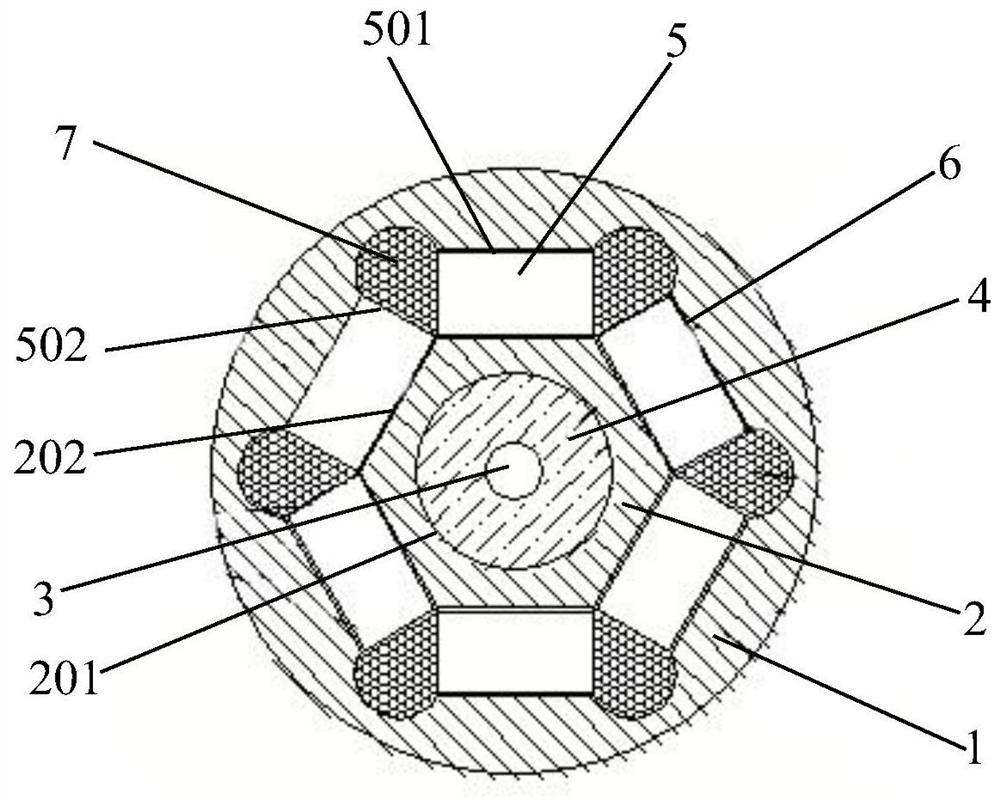
[0018] see Figure 1-Figure 2 , the embodiment of the present invention discloses an array piezoelectric ceramic transducer, comprising:

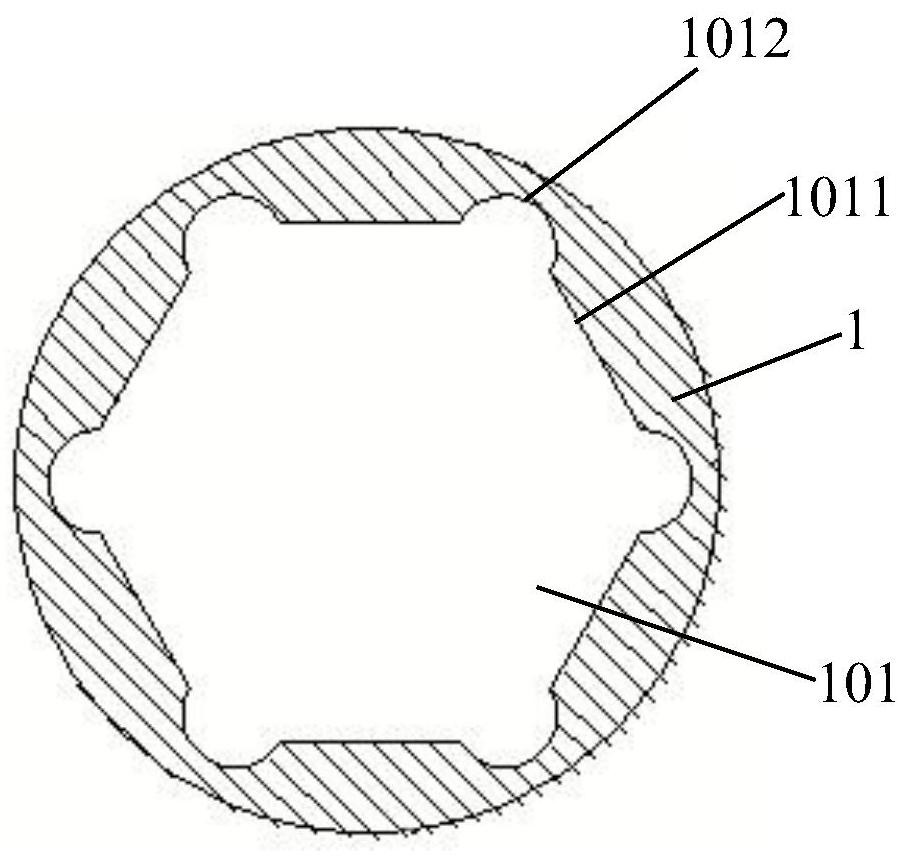
[0019] The outer polarity brass shell 1, the space inside the outer polarity brass shell 1 is the accommodation cavity 101, the inner wall surface of the accommodation cavity 101 is a polygonal structure, and the space between two adjacent first straight sides 1011 of the polygonal structure is concave Arc 1012 transition ...


PUM


Abstract

The invention discloses an array piezoelectric ceramic transducer, which comprises an external polarity brass shell, the internal space of the external polarity brass shell is an accommodating cavity, the inner wall surface of the accommodating cavity is of a polygonal structure, and two adjacent first straight edges of the polygonal structure are in concave arc transition connection; an internal polarity polygonal brass column formed by one-time pressing and sintering molding is arranged in the middle of the accommodating cavity, and a mounting hole is formed in the middle of the internal polarity polygonal brass column; a magnetostrictive waveguide wire is bonded with the hole wall of the mounting hole through insulating filling glue; the two long edges of each rectangular piezoelectric ceramic piece are respectively bonded with the first straight edge of the accommodating cavity and the second straight edge of the internal polarity polygonal brass column through conductive silver adhesives; the short edges of every two adjacent rectangular piezoelectric ceramic pieces are bonded through a gap between the two adjacent rectangular piezoelectric ceramic pieces and anti-stress insulation filling glue loaded in concave arcs. The transducer is simple and firm in structure, the ceramic chip is easy to form, the size is large, and the output charge is large.

Description

technical field [0001] The invention relates to the technical field of transducers, and more specifically relates to an array piezoelectric ceramic transducer applied to the wave transmission signal test of a magnetostrictive liquid level gauge. Background technique [0002] A transducer is a device that converts electrical, mechanical, or acoustic energy from one form of energy to another. The commonly used piezoelectric ceramic structure has certain disadvantages: first, the contact surface between the ceramic sheet and the internal polarity and external polarity is not vertical contact, usually the contact between the arc and the straight edge, and the conductive silver glue is used for solid connection. The joint point is not strong enough, and the force is not uniform enough; second, usually 12 corresponding ceramic sheets are connected in series, and too many ceramic sheets in series make the unit volume of the ceramic sheet too small and the effective volume is too sm...

Claims


Application Information

Patent Timeline
IPC IPC(8): H01L41/047H01L41/113H01L41/187H01L41/43G01F23/72
CPCG01F23/72H10N30/87H10N30/30H10N30/853H10N30/097
Inventor 沃栩王新光王伟光
Owner 德州英卡纳仪表有限公司
Features
  • R&D
  • Intellectual Property
  • Life Sciences
  • Materials
  • Tech Scout
  • Unparalleled Data Quality
  • Higher Quality Content
  • 60% Fewer Hallucinations
Learn More