
Non-contact power supply system of power monitoring equipment

A technology for power monitoring and power supply systems, applied in battery circuit devices, protection against overcurrent, current collectors, etc. High degree of integration, safe volume, and the effect of protecting the circuit

Pending Publication Date: 2021-12-03
ELECTRIC POWER RES INST OF GUANGXI POWER GRID CO LTD
View PDF6 Cites 0 Cited by
  • Summary
  • Abstract
  • Description
  • Claims
  • Application Information

AI Technical Summary

Problems solved by technology

Chinese patent CN112491167B-Microwave wireless power supply system and method applied to power grid transmission line monitoring equipment uses microwaves to transmit power. It is an online monitoring device on high-voltage transmission lines, but microwaves are used to transmit energy. Although the transmission efficiency is very high, but When transmitting high-power electric energy, there are high requirements for antenna equipment.
[0004] Therefore, it has limitations on the transmission power; in addition, due to the strong radiation loss of microwaves and lasers, it is not suitable for charging electronic devices
Moreover, the Chinese patent CN112491167B-microwave wireless power supply system and method applied to power grid transmission line monitoring equipment does not set a high-voltage isolation scheme, and the safety is not high

Method used


Image

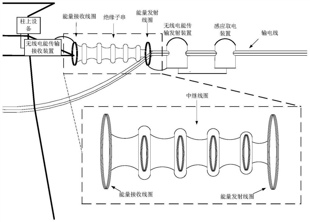
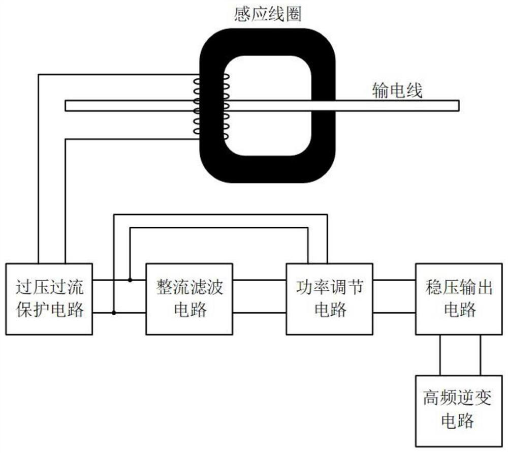
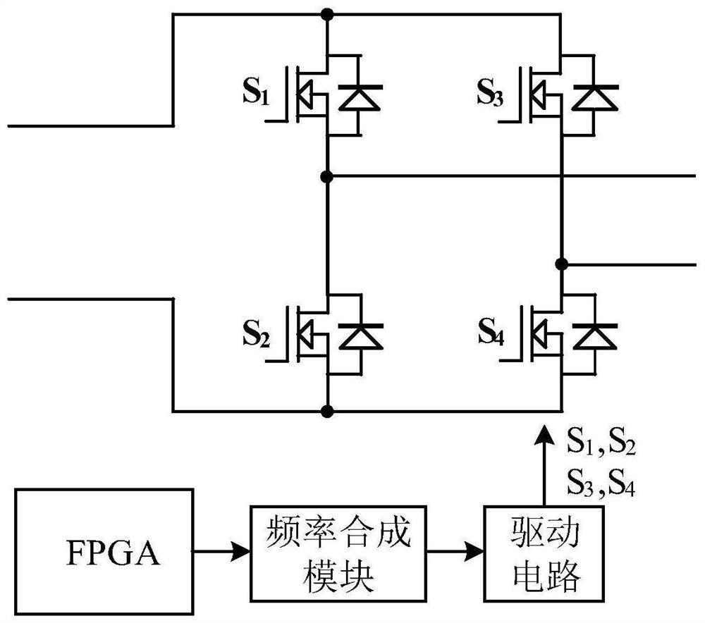
  • Non-contact power supply system of power monitoring equipment
  • Non-contact power supply system of power monitoring equipment
  • Non-contact power supply system of power monitoring equipment

Examples


Embodiment Construction

[0038] In order to better understand the present invention, the present invention will be further described below in conjunction with accompanying drawing and specific embodiment:

[0039] The following will clearly and completely describe the technical solutions in the embodiments of the present invention with reference to the accompanying drawings in the embodiments of the present invention. Obviously, the described embodiments are some of the embodiments of the present invention, but not all of them. Based on the embodiments of the present invention, all other embodiments obtained by persons of ordinary skill in the art without making creative efforts belong to the protection scope of the present invention.

[0040] It should be understood that when used in this specification and the appended claims, the terms "comprising" and "comprises" indicate the presence of described features, integers, steps, operations, elements and / or components, but do not exclude one or Presence ...


PUM


Abstract

The invention belongs to the technical field of wireless power supply and relates to a non-contact power supply system of power monitoring equipment. The system comprises an induction power taking device, a wireless electric energy transmission emitting device, an insulator string and a wireless electric energy transmission receiving device. According to the non-contact power supply system of the power monitoring equipment of the invention, the insulator string is used as a high-voltage isolation component for wireless power transmission and can fix an intermediate coil, so that double functions are achieved, the cost is saved, and the size of the system is reduced; a multi-stage relay coil is used for wireless transmission of electric energy, based on the size of insulators, and the insulators are used as a non-contact channel for wireless energy transmission between the induction power taking device and the power monitoring equipment, so that the size and the weight of the whole device are reduced, and energy can be transmitted while high-voltage isolation is realized. Compared with a microwave transmission mode, the system is safer and smaller in size.

Description

technical field [0001] The invention relates to the technical field of wireless power supply, in particular to a non-contact power supply system for power monitoring equipment. Background technique [0002] At present, with the rapid development of China's electric power industry, the safe operation of the power system is becoming more and more important. The long-distance ultra-high voltage transmission method is the main artery of the power system, and its operation safety directly determines the safety and efficiency of the power system. In order to make the power grid gradually Moving towards automation and intelligence requires a large number of monitoring equipment and sensors. There are mainly three traditional processing methods at home and abroad: one is solar power supply. As a renewable clean energy, the power supply quality of this method is vulnerable to weather Moreover, the life of the battery is related to the number of charge and discharge cycles. The theore...

Claims


Application Information

Patent Timeline
Patent Type & Authority Applications(China)
IPC IPC(8): H02J50/00H02J50/10H02J50/40H02J50/50H02J9/06H02J7/02H02H3/08
CPCH02J50/005H02J50/10H02J50/50H02J50/502H02J50/40H02J9/068H02J7/02H02H3/08
Inventor 冯玉斌崔志美黄志都邬蓉蓉唐捷
Owner ELECTRIC POWER RES INST OF GUANGXI POWER GRID CO LTD
Learn More