Gate valve machining process and device
A processing device and gate valve technology, applied in metal material coating process, melt spraying, coating and other directions to achieve effective and fast clamping effect
- Summary
- Abstract
- Description
- Claims
- Application Information
AI Technical Summary
Problems solved by technology
Method used
Image
Examples
Embodiment 1
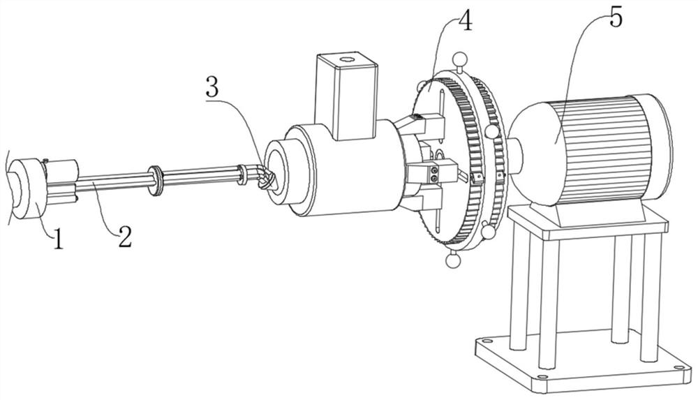
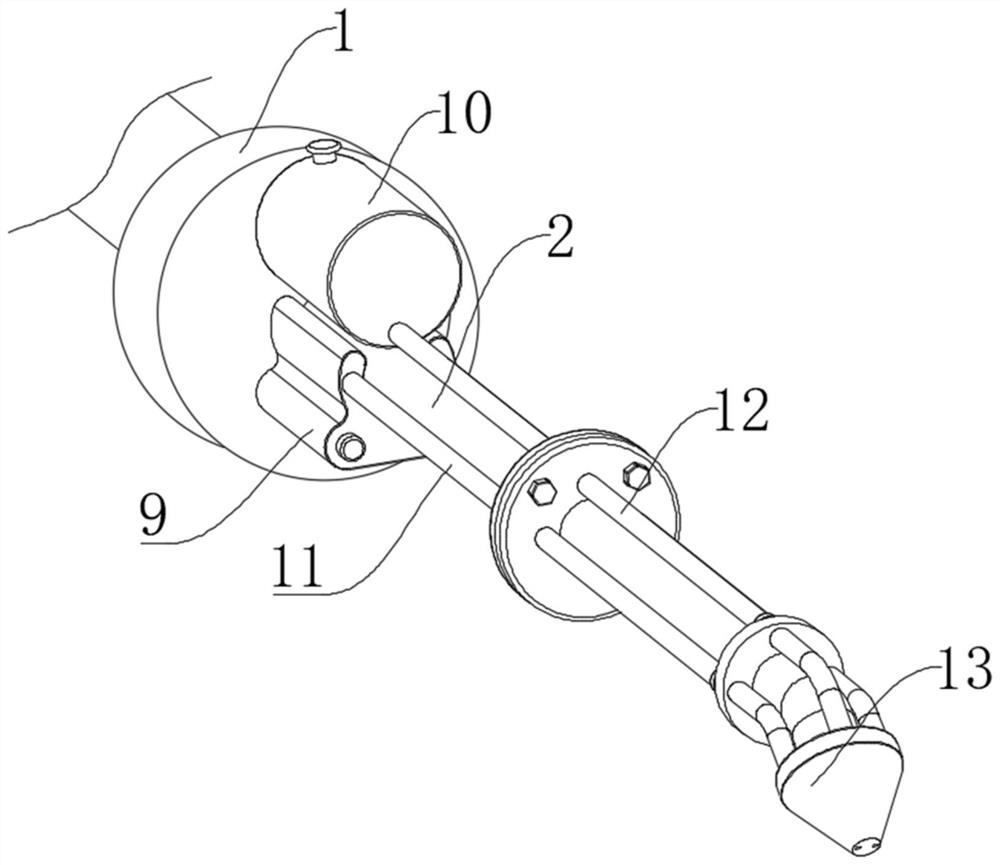
[0033] see Figure 1-8 , a gate valve processing device in the illustration, including a laser generator 1 and a conduit 2, wherein the surfaces of the laser generator 1 and the conduit 2 are coated with an anti-oxidation layer and a wear-resistant layer, and the side end of the laser generator 1 is provided with The connecting rod that is convenient to connect with the mechanical arm, the injection mechanism 3, the injection mechanism 3 that can process the inside of the valve body is installed on the side end of the conduit 2; the clamping mechanism 4, the clamping mechanism 4 that can clamp the valve body is installed At the side end of the spraying mechanism 3 ; the drive mechanism 5 , which drives the clamping mechanism 4 to rotate, is installed at the side end of the clamping mechanism 4 .
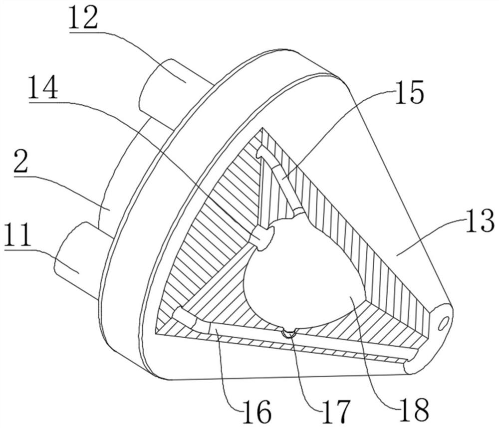
[0034] The injection mechanism 3 includes a heat-resistant spray head 13 fixedly installed on the right side of the conduit 2, the left end of the conduit 2 is fixedly embedded in th...
Embodiment 2
[0040] see Figure 6-Figure 8 , this embodiment is further described for Example 1. The passive member 6 includes a passive block 33 that is movably installed at the left and right ends of the turntable 22. The inner side of the passive block 33 is fixedly installed with a rotating shaft 35, and the rotating shaft 35 runs through the turntable 22 movably. A mainspring 36 is installed on the outer surface corresponding to the inner side of the rotating shaft 35, and the outer and inner ends of the mainspring 36 are fixedly connected with the rotating disk 22 and the rotating shaft 35. Ratchet 41 is movable connection, and the inboard of passive block 33 is installed limit piece 7, and in the process of clockwise rotation of rotating disk 22, can drive passive block 33 to rotate simultaneously, and passive block 33 under the effect of mainspring 36, makes passive block 33 Attached to the outer surface of the ratchet 41 to move.
[0041] In this embodiment: the winding force exe...
Embodiment 3
[0043] see Figure 7 and Figure 8 , The embodiment is further described for other embodiments, the limiting member 7 includes a movable plate 38 movably embedded in the inner side of the passive block 33, the inner side of the movable plate 38 is fixedly installed with a limiting rod 37, and the limiting rod 37 moves through the passive block 33 , the inner side of the turntable 22 is provided with a positioning hole 42, and the left end of the limit rod 37 is movably fitted with the positioning hole 42, the right end of the limit rod 37 is fixedly equipped with a handle 40, and the inner side of the passive block 33 corresponds to the movable plate The right end of 38 is equipped with a spring 39. When the valve body needs to be loosened, the user can pull up the passive block 33 through the linkage column 34. When the limit rod 37 touches the positioning hole 42, the spring 39 generates The elastic force of the movable plate 38 and the stop bar 37 can be pushed through, so...
PUM
 Abstract
Description
Claims
Application Information
 - R&D
- Intellectual Property
- Life Sciences
- Materials
- Tech Scout
- Unparalleled Data Quality
- Higher Quality Content
- 60% Fewer Hallucinations
Browse by: Latest US Patents, China's latest patents, Technical Efficacy Thesaurus, Application Domain, Technology Topic, Popular Technical Reports.
© 2025 PatSnap. All rights reserved.Legal|Privacy policy|Modern Slavery Act Transparency Statement|Sitemap|About US| Contact US: help@patsnap.com


