Built-in miniature balloon joint distraction device

A built-in, balloon technology, applied in the field of medical devices, can solve the problems of high replacement cost, increased replacement cost, and inflexibility, and achieve the effect of large deformation by external force, small deformation by external force, and avoiding damage

Pending Publication Date: 2021-12-10
XIN HUA HOSPITAL AFFILIATED TO SHANGHAI JIAO TONG UNIV SCHOOL OF MEDICINE
View PDF2 Cites 1 Cited by
  • Summary
  • Abstract
  • Description
  • Claims
  • Application Information

AI Technical Summary

Problems solved by technology

The beneficial effect that this patent application document obtains is: (1) reduces patient's misery and trauma to patient's joint; (2) increases surgical field of view, facilitates operation of operation; The front end is curved, and the top of the suction tube is provided with several suction holes, so that the blood and smoke generated during the operation can be sucked out of the suction tube in time without causing trauma to the joint tissue; the solution provided by this patent application The balloon and the suction tube are placed in the wall of the channel to support expansion and suction; but it is obvious that its position is relatively fixed and extremely inflexible, and it is integrated with the wall of the channel. It also increases the cost of replacement
[0007] Chinese patent application CN204181584U discloses a joint synovial cavity endoscopic device, including a lens barrel, a CCD camera and an LED light source are arranged on the top of the lens barrel, a handle is arranged at the end of the lens barrel, and a Video line and light source line, one end of the video line is connected to the CCD camera, the other end protrudes from the inner cavity of the handle and is connected to a display, one end of the light source line is connected to the LED light source, and the other end protrudes from the inner cavity of the handle It is also connected with an LED light source generator, and a three-lumen tube is bundled on the outer wall of the lens barrel. Inside the three-lumen tube, there are a suction tube, a water injection tube and an inflatable tube. The front end of the inflatable tube is provided with a balloon. The balloon is fixed at the front end of the lens barrel; its beneficial effects are: (1) relieves the pain of the patient; (2) effectively expands the surgical field of view; (3) facilitates the operation; (4) facilitates washing; (5) facilitates control; but it also has a complex structure and low flexibility, and cannot be adjusted and selected according to the needs of the operation, and the replacement cost is high

Method used


Image

  • Built-in miniature balloon joint distraction device
  • Built-in miniature balloon joint distraction device
  • Built-in miniature balloon joint distraction device

Examples


Embodiment 1

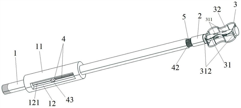
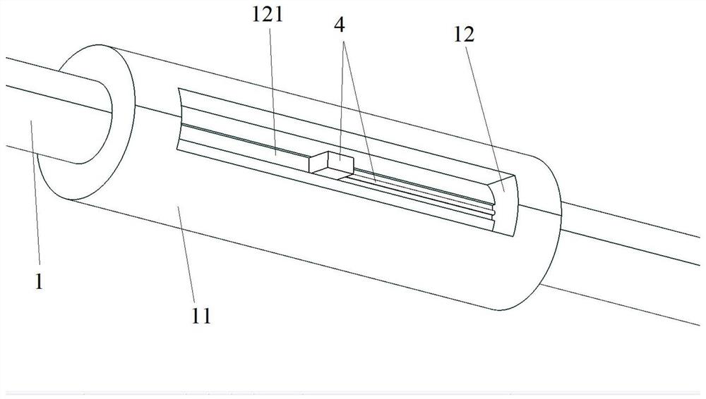
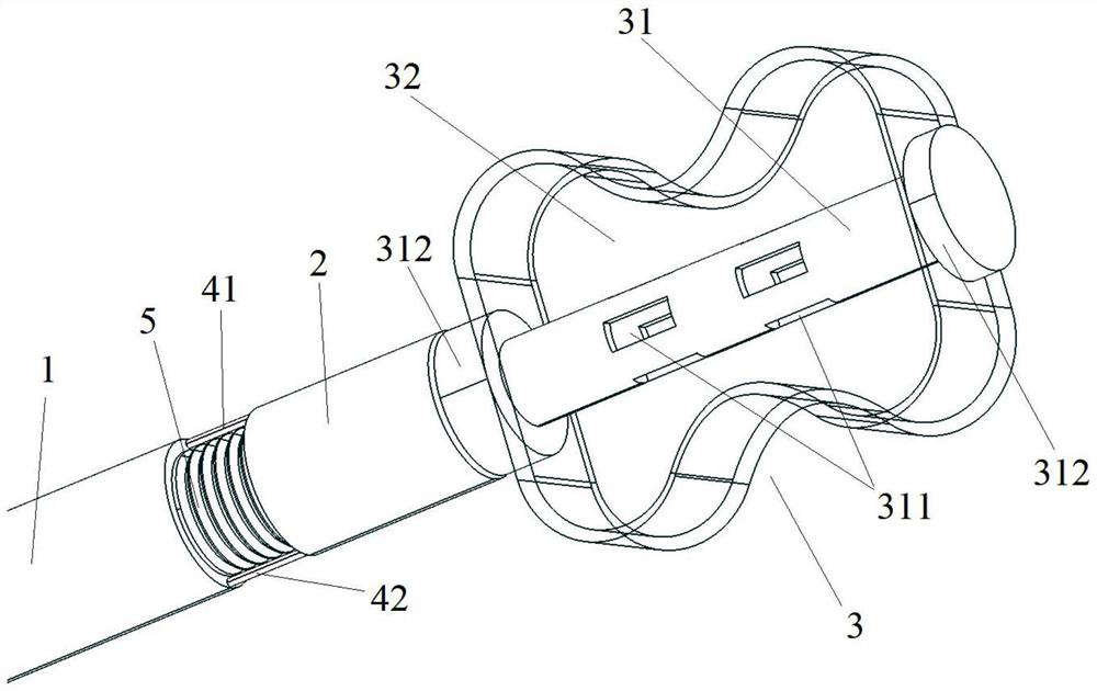
[0041] Please see attached figure 1 , with figure 1It is a three-dimensional schematic diagram of a built-in micro-balloon joint expansion device of the present invention; a built-in micro-balloon joint expansion device includes a catheter body 1, a swing assembly 2, and a balloon 3; please refer to the attached figure 2 , with figure 2 It is a schematic diagram of the control handle of a built-in micro-balloon joint expansion device of the present invention; the catheter body 1 is a lumen structure with openings at both ends, and a control handle 11 is sleeved on the tube wall. 1 One port is exposed to the outside of the joystick 11, the side of the joystick 11 is provided with two symmetrically arranged operation grooves 12, and the operation groove 12 is provided with a guide groove 121, on which the control assembly 4 is connected , the control assembly 4 includes a first guide wire 41 and a second guide wire 42; the first guide wire 41 and the second guide wire 42 are...

Embodiment 2

[0045] Please see attached Figure 5 , attached Figure 6 , with Figure 5 It is a partial cross-sectional schematic diagram of another built-in micro-balloon joint expansion device of the present invention; Figure 6 It is a partial cross-sectional view of the balloon of another built-in micro-balloon joint distraction device of the present invention. This embodiment is basically the same as Embodiment 1, the difference is that the catheter body 1 is also provided with a first sleeve 13 inside, and the first sleeve 13 is a hose structure, one end of which is arranged on the The center position of the swing assembly 2, the other end of which passes through the tube wall of the catheter body 1, can be connected with external equipment; the inside of the balloon skeleton 31 is provided with a second sleeve 313, and the second sleeve 313, one end of which is fixedly connected with one of the through holes 311 on the tube wall of the balloon skeleton 31, and the other end is se...


PUM


Abstract

The invention relates to a built-in miniature balloon joint distraction device, which comprises a catheter body, a swing assembly and a balloon, wherein the catheter body and the swing assembly are of a pipe cavity structure; one end of the swing assembly is movably connected with one end of the catheter body through a flexible pipeline, and the other end of the swing assembly can be connected with external equipment; an operating handle is arranged on the catheter body; a control assembly is arranged on the operating handle and is used for controlling the pointing direction of the swing assembly; the balloon comprises a balloon body and a balloon skeleton; the balloon framework is of a pipe cavity structure with an opening in one end; through holes are arranged on the pipe wall of the balloon framework; one part of the balloon framework is located in the balloon body; the through holes communicates with the balloon body; and one end of the balloon framework is detachably connected with one end of the swing assembly. The built-in miniature balloon joint distraction device has the advantages that the structure is simple, flexibility is high, cost can be effectively controlled, the operation view of an operator is increased, a better operation environment is obtained, an operation success rate is increased, and arthroscopic operation difficulty is reduced.

Description

technical field [0001] The invention relates to the technical field of medical instruments, in particular to a built-in miniature balloon joint expansion device. Background technique [0002] Arthroscopy technology originated in Japan in the early 20th century, and has been greatly developed in the United States and other countries since the 1970s. In the past few decades, arthroscopy has had a revolutionary impact on the diagnosis and treatment of intra-articular diseases. It has been widely used clinically and has become a routine diagnosis and treatment method in bone and joint surgery. Compared with other examinations, arthroscopy can directly observe the lesion, and has obvious advantages in the movement system. In the case of mild interference with the structure and function of healthy tissues, it can be operated in a small area and channel, and the examination can be performed under direct vision. Hidden parts that cannot be observed are highly intuitive and less tra...

Claims


Application Information

Patent Timeline
IPC IPC(8): A61B17/02
CPCA61B17/0218A61B17/025
Inventor 李海代振振于颖
Owner XIN HUA HOSPITAL AFFILIATED TO SHANGHAI JIAO TONG UNIV SCHOOL OF MEDICINE
Why Eureka
Try Eureka